Manual control with force-feedback for probe microscopy-based force spectroscopy

a probe microscopy and force spectroscopy technology, applied in the field of probe microscopes, can solve the problems of inability to predict piezoelectric scanners completely, inability to detect the interaction force of tipsamples, and inability to accurately detect the mechanical behavior of thin films from known materials properties

Inactive Publication Date: 2006-03-21
BRUKER NANO INC
View PDF9 Cites 28 Cited by
  • Summary
  • Abstract
  • Description
  • Claims
  • Application Information

AI Technical Summary

Benefits of technology

[0041]The preferred embodiment overcomes the drawbacks of prior art systems by providing a force scanning probe microscope (FSPM) that combines a flexured Z stage and a piezoelectric tube XY scanner with a manual control device that allows a user to manipulate tip-sample separation according to an alert feedback, such as a tactile or audio alert. More particularly, the manual control device is preferably a rotatable knob having a range of motion greater than 180°. Moreover, the alert feedback is preferably provided via a resistance device, such as a brake that alters the torque required to turn the knob in response to a measured force.

Problems solved by technology

However, these forces are extremely small.
For example, as microstructures such as integrated circuits continue to shrink, exploring the mechanical behavior of thin films from known properties of the materials becomes increasingly inaccurate.
However, PMs also include devices such as molecular force probes (MFPs) that similarly use a probe to characterize sample properties but do not scan.
Although SPMs are particularly useful in making such measurements, there are inherent problems with known systems.
Overall, the motion generated by such piezoelectric scanners is not entirely predictable, and hence such scanners have significant limitations.
Piezoelectric scanners also “creep,” which means that they continue to extend or retract for a period of time after the applied drive voltage has stopped changing.
Those skilled in the art recognize that this represents a serious limitation on the range of operating speeds for which the scanner is useful.
Any one or more of these limitations clearly jeopardize the integrity of the tip-sample motion, and therefore the corresponding data collected is of marginal usefulness.
Alternative means of relative tip-sample motion exist that address these concerns, although they can create new problems.
However, adding sensors to a scanner only detects, not corrects, these undesirable motions.
Nevertheless, although the above may seem to suggest a design including closed-loop flexure stages in all three axes, in practice such a design has significant drawbacks.
Among the disadvantages of a three-flexure stage design, is that 3-axis flexure stages are much larger than a typical piezoelectric tube scanner of similar range due to the added mass and volume of the constraining mechanism and sensors.
In practice, larger designs more readily couple outside vibrational and acoustic noise sources into the motion of the scanner, which significantly degrades the scanners usefulness for force spectroscopy.
Closed-loop flexure stages are also significantly more expensive than piezoelectric tube scanners of similar range.
Therefore, the use of flexure stages for all three axes is not desirable for the design of a compact, low-noise, relatively inexpensive instrument.
There are also drawbacks associated with the methods employed to make conventional force curve measurements.
In this regard it is notable that conventional systems often lack flexibility in making measurements that are non-cyclic.
However, the technique is not well-suited to exploratory type measurements since it is not always obvious at the beginning of an experiment what the appropriate measurement parameters should be set to.
It becomes even more difficult to estimate distance, speeds, and pause times in more complex experiments where, for instance, the user may wish to partially stretch a molecule, then pause to let it relax, and then decrease the probe-sample distance to allow the molecule to re-fold.
However, merely having manual control of the probe-sample separation is not enough to make the device useful.
However, this device is not optimized for single molecule force measurements because, as appreciated by those skilled in the art, the ability to change probe-sample separation in only one-axis is difficult with a three-axis device.
Furthermore, making fine adjustments to the position of the end of the stylus in free air is difficult at best, even with steady hands.
Moreover, the useable range and sensitivity of such a device is inherently limited by the dimensions of the device.
This drawback with respect to sensitivity and control is the same one that limits the usefulness of another probe microscope haptic device.
But again, this device is of limited utility since the range of motion has a definite limit.

Method used


Image

  • Manual control with force-feedback for probe microscopy-based force spectroscopy
  • Manual control with force-feedback for probe microscopy-based force spectroscopy
  • Manual control with force-feedback for probe microscopy-based force spectroscopy

Examples


Embodiment Construction

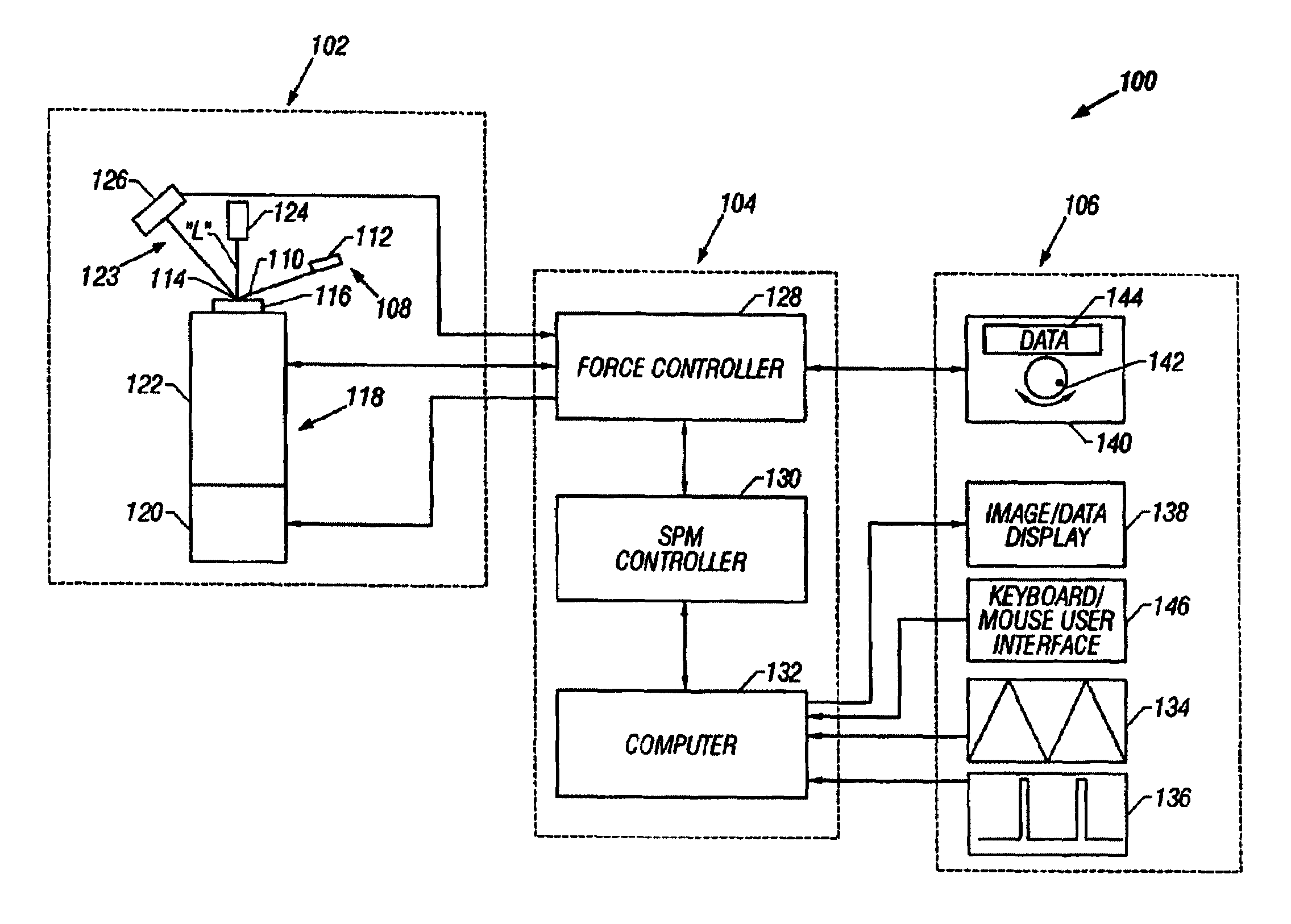
[0080]Turning initially to FIG. 6, a force scanning probe microscope (FSPM) 100 that provides highly accurate force measurements, including force volume measurements, with a high degree of data acquisition flexibility is illustrated. FSPM 100 includes an atomic force microscope (AFM) 102, a data acquisition and control system 104, and a user interface 106. Probe microscope 102 includes a probe 108 having a cantilever 110 extending from a substrate 112. Cantilever 110 includes a free end to which a tip 114 is coupled so that it extends generally orthogonal to cantilever 110. Probe 108 is placed in a support (not shown), such as a conventional probe holder, thus collectively defining a probe assembly.

[0081]Next, a sample 116 is mounted on a piezoelectric scanner 118 in a conventional fashion. The sample 116 may, for instance, comprise a single molecule of a substance of interest. In the preferred implementation, scanner 118 is used to actuate the sample in three substantially orthogon...


PUM

PropertyMeasurementUnit
lengthaaaaaaaaaa
sizeaaaaaaaaaa
sizeaaaaaaaaaa

Abstract

A probe microscope includes a probe and a scanner, the scanner generating relative motion between a probe and a sample. In addition, a manual input device is provided to control a separation between a sample and a probe. The detector is used to generate a signal related to movement of the probe (for example, deflection). Moreover, the microscope has an alerting device that is responsive to the signal to provide feedback to an operator, the feedback being indicative of interaction between the sample and the probe. Preferably, the manual input device is a rotatable knob. Also, the alerting device is preferably a mechanical resistance device coupled to the knob to provide the feedback to the user.

Description

BACKGROUND OF THE INVENTION[0001]1. Field of the Invention[0002]The present invention is directed to probe microscopes, and more particularly, a probe microscope apparatus and method for sensing tip-sample interaction forces.[0003]2. Description of Related Art[0004]Developments in nanotechnology have enabled mechanical experiments on a broad range of samples including single molecules, such that fundamental molecular interactions can be studied directly. The mechanical properties of biological molecules, in particular, such as actin filaments and DNA has lead to the development of a range of instrumentation for conducting these studies. In this regard, systems and methods differing in force and dynamic ranges currently being used include magnetic beads, optical tweezers, glass microneedles, biomembrane force probes (BFP), scanning probe microscopy (SPM), and atomic force microscopy (AFM).[0005]With a force sensitivity on the order of a few pico-Newtons (pN=10−12N), an AFM is an exce...

Claims


Application Information

Patent Timeline
Patent Type & Authority Patents(United States)
IPC IPC(8): G01N13/10G01Q10/00G01Q10/04G01Q10/06G01Q60/24
CPCB82Y35/00G01Q10/065G01Q10/04
Inventor STRUCKMEIER, JENSGOTTHARD, DOUGOHLER, BEN
Owner BRUKER NANO INC
Why Eureka
Try Eureka