
Process for degassing an aqueous plating solution

a technology of aqueous plating solution and degassing process, which is applied in the direction of liquid degasification, separation process, and membrane, can solve the problems of reducing the electrical conductivity of the copper pathway formed on the semiconductor surface, adversely affecting the acceptability of the deposited copper film, etc., to facilitate the plating of copper and prevent the intrusion of liquid through the pores of the membran

Inactive Publication Date: 2006-03-21
ENTEGRIS INC
View PDF15 Cites 22 Cited by
  • Summary
  • Abstract
  • Description
  • Claims
  • Application Information

AI Technical Summary

Benefits of technology

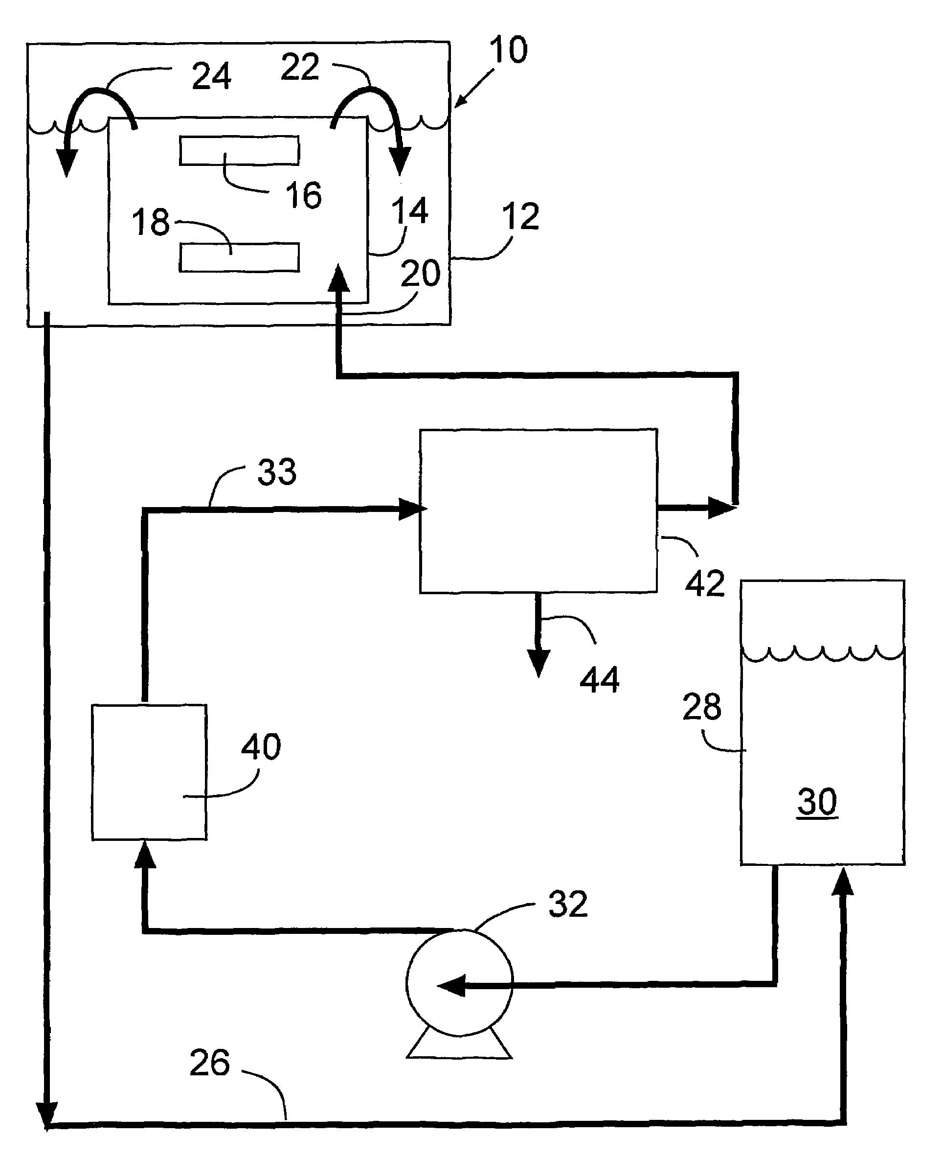
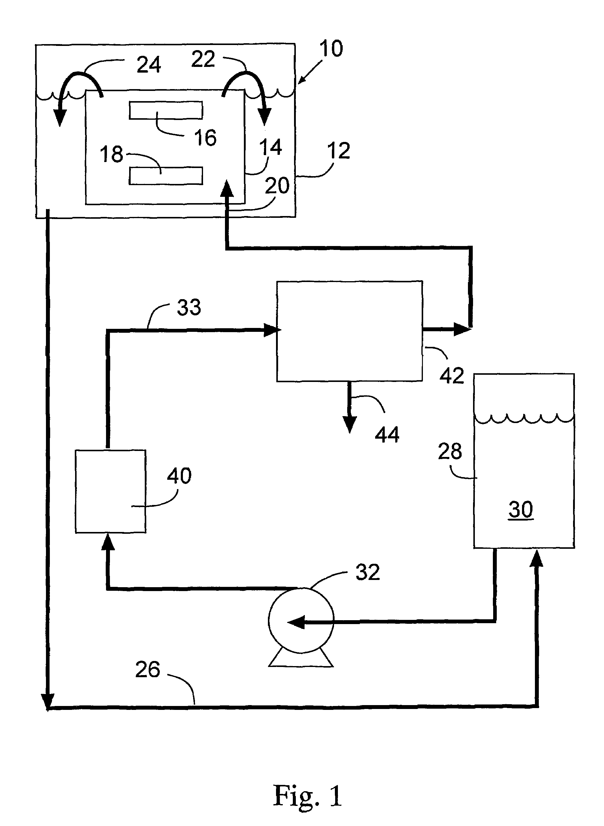
[0010]In accordance with this invention, a copper anode and a cathode comprising a substrate such as a silicon wafer, upon which an electrically conductive copper pathway is to be plated, are immersed in an acidic aqueous copper plating bath in a plating step. The plating bath contains organic additives which facilitate plating of copper including accelerators, brighteners, suppressors and levelers. Aqueous copper plating solution is directed to the plating step by being passed through a filter to remove particles therein and then through the hollow fiber membrane degasser to remove dissolyed oxygen from the solution. Degassing is effected with the hollow fiber membranes under conditions that intrusion of liquid through the pores of the membranes is prevented. The plating solution is removed from the plating bath and is directed to a reservoir for the solution where its composition can be monitored to determine whether additional organic additive or acid should be added thereto in order to maintain the desired composition which is efficient for attaining satisfactory copper plating in the plating step.

Problems solved by technology

Accelerated organic additive consumption changes the chemical composition of the bath which, in turn, can adversely affect the acceptability of the deposited copper film.
The presence of dissolved gas such as oxygen in the plating bath also can cause the formation of undesirable microvoids in the plated copper film This, in turn, can cause reduced electrical conductivity in the copper pathways formed in the semiconductor surface.

Method used


Image

  • Process for degassing an aqueous plating solution
  • Process for degassing an aqueous plating solution
  • Process for degassing an aqueous plating solution

Examples


example 1

Experiments Without Degasser

[0029]Experiments were performed in a copper electroplating tool. The plating solution from a reservoir (˜75 liters) is circulated (˜17 liters / min flow rate) through a plating cell containing a silicon wafer cathode and a copper anode. The solution additives are maintained at adequate level by periodically analyzing the bath for composition and adding the make up amount.

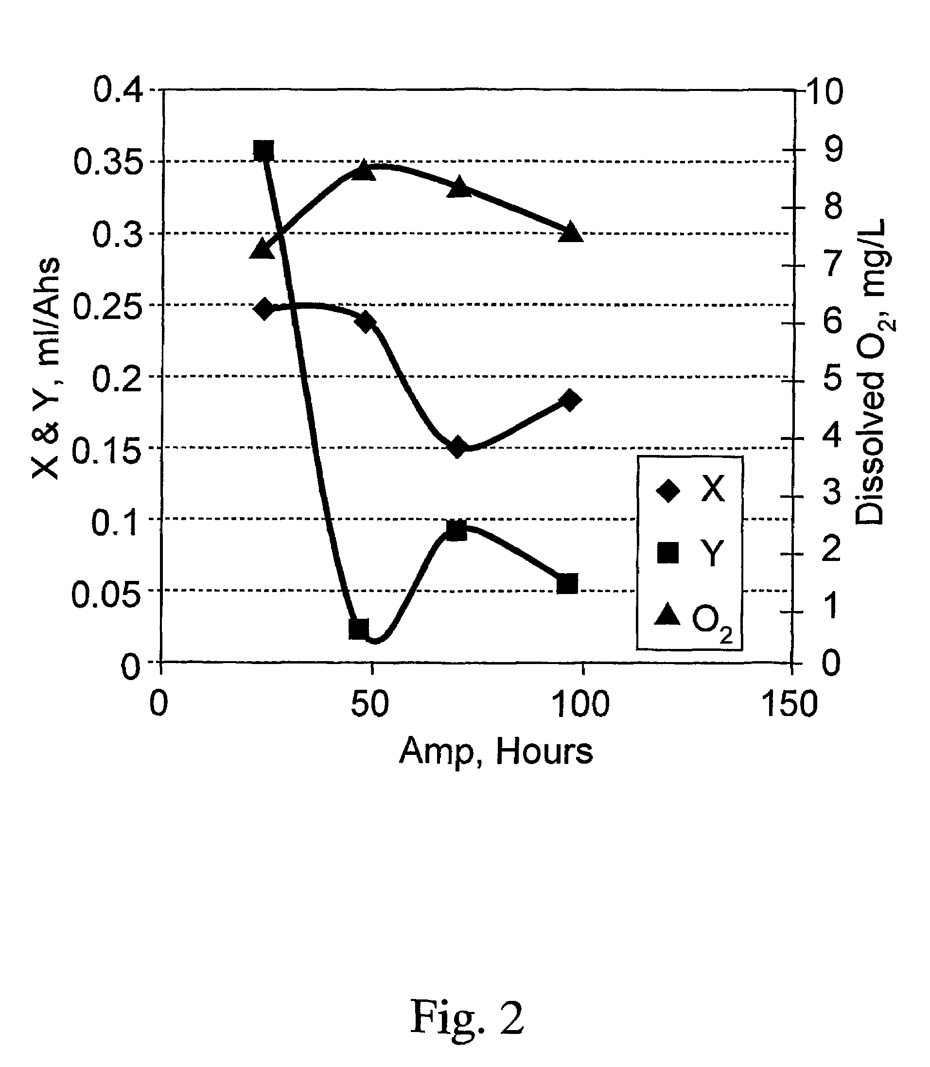
[0030]An analysis of two key additive components and dissolved oxygen in the solution, for one week, is profiled in FIG. 2 wherein X and Y are two different organic additives. FIG. 2 plots Amp. Hours vs. additive concentration or oxygen concentration. As shown in FIG. 2, the X and Y additives were consumed in the presence of oxygen.

example 2

Use of Single Degasser

[0031]A second set of experiments were conducted as described in Example 1 but with a degasser unit turned on (˜26 Hg vacuum). The degasser unit included 10 inch hollow fiber skinned PFA ultrafiltration membranes. The dissolved oxygen and additive concentration in the bath were monitored as profiled in FIG. 3.

[0032]As shown in FIG. 3, the process with a degasser lowers the dissolved oxygen in the solution by about 1 ppm. The concentration of component X in the additive is less affected (consumed) with the degasser or without the degasser. These results are shown in FIG. 4. The data show that with the degasser on, the consumption of the additive component X was less.

example 3

Three Degassers and Nitrogen Blanket

[0033]Three degasser modules of the type used in Example 2 were installed (in a parallel configuration) in the copper plating unit. The objective was to determine incremental improvements in degassing efficiency and its effect on the additive consumption, over time.

[0034]The system performance was also improved by reducing / eliminating the sources of oxygen entrainment into the plating solution at the cell overflow, drain pipe return line, and the solution reservoir by infusing nitrogen and covering these areas with appropriate plastic lids or plastic sheeting.

[0035]Preliminary results indicate the degassing efficiency increased to about 40% with three degasser (vs 10–15% with one degasser). Upon adding / covering various exposed areas with a nitrogen blanket, there was a significant improvement in the degassing efficiency in ˜50%. The bath samples were analyzed for additive consumption. The results show a dramatic decline in the additive consumption...


PUM

PropertyMeasurementUnit
surface energyaaaaaaaaaa
lengthaaaaaaaaaa

Abstract

A process for removing oxygen from a copper plating solution is provided. The solution is passed through a degasser comprising a shell and hollow hydrophobic fiber porous membranes wherein the shell while a vacuum is drawn on the surfaces of the fibers opposite the fiber surfaces contacted by the solution. Gas passed through the fiber walls while liquid is prevented from infiltrating the fiber pores. The composition of the solution is monitored so that the composition can be retained substantially constant by adding components of the solution as needed.

Description

[0001]This application claims the benefit of Provisional Application No. 60 / 267,295, filed Feb. 7, 2001.FIELD OF THE INVENTION[0002]This invention relates to a process for removing all dissolved gasses from aqueous electroplating and electroless plating bath solutions. More particularly, this invention relates to a process for removing dissolved gasses including oxygen from aqueous copper plating and electroless plating bath solutions.BACKGROUND OF THE INVETION[0003]Recently copper electrochemical deposition processes have become available to form electrically conductive pathways on semiconductor chips. Copper electrochemical deposition process for the damascene structures of high aspect ratios for semiconductor manufacturing is a new application of the conventional electroplating process. The electroplating of high aspect ratio devices involves the use of copper plating to fill high aspect ratio sub-micron trenches and vias positioned on semiconductor chips. An acidic copper sulfat...

Claims


Application Information

Patent Timeline
Patent Type & Authority Patents(United States)
IPC IPC(8): B01D19/00B01D53/22B01D61/00B01D63/02B01D71/32B01D71/36C23C18/38C25D3/38C25D21/04C25D21/06C25D21/12
CPCB01D19/0031B01D19/0068B01D63/02C25D3/38C25D21/12B01D71/32B01D2313/90B01D19/00
Inventor PAREKH, BIPINLY, SAKSATHAWU, QUNWEI
Owner ENTEGRIS INC
Learn More