Medical laser apparatus and diagnostic/treatment apparatus using the medical laser apparatus

a laser apparatus and laser technology, applied in the field of medical laser equipment, can solve the problems of difficult control of the laser light projected, difficult to have a wavelength which coincides, and is not possible for the gas laser, and achieves the effects of good exciting efficiency, easy maintenance, and narrow fall width

Inactive Publication Date: 2006-03-21
PANASONIC CORP
View PDF26 Cites 14 Cited by
  • Summary
  • Abstract
  • Description
  • Claims
  • Application Information

AI Technical Summary

Benefits of technology

[0018]The object of the present invention is therefore to provide, with eliminating the aforementioned drawbacks of the conventional apparatuses, a compact and inexpensive medical laser apparatus which achieves laser light o

Problems solved by technology

A drawback of the conventional diagnostic/treatment apparatus of cancers resides in the fact that the wavelength of the projected laser light is difficult to control.
Generally, it is not possible for the gas laser (Table 1) to meet the absorption band of a plurality of the photosensitizers.
Moreover, it is difficult for the gas laser to have a wavelength which coincides with the maximum absorption wavelength of even a single photosensitizer.
In the case where the dye laser is used, therefore, the diagnostic/treatment apparatus becomes disadvantageously bulky in size to accommodate a plurality of different kinds of coloring matter solutions and a switching of the solutions.
A second disadvantage of the diagnostic/treatment apparatus using the dye laser is that the solution of a coloring matter of the dye laser easily deteriorates, inviting a change of the wavelength of the resultant laser light or a decrease of the output.
Since the safety of the laser light is an essential and indispensable condition to ensure the effect of PDD and especially PDT, a substantial problem of the dye laser arises when the solution of the coloring matter sh

Method used


Image

  • Medical laser apparatus and diagnostic/treatment apparatus using the medical laser apparatus
  • Medical laser apparatus and diagnostic/treatment apparatus using the medical laser apparatus
  • Medical laser apparatus and diagnostic/treatment apparatus using the medical laser apparatus

Examples


first embodiment

[First Embodiment]

[0038]A medical laser apparatus according to a first embodiment of the present invention will be discussed hereinbelow with reference to the accompanying drawings.

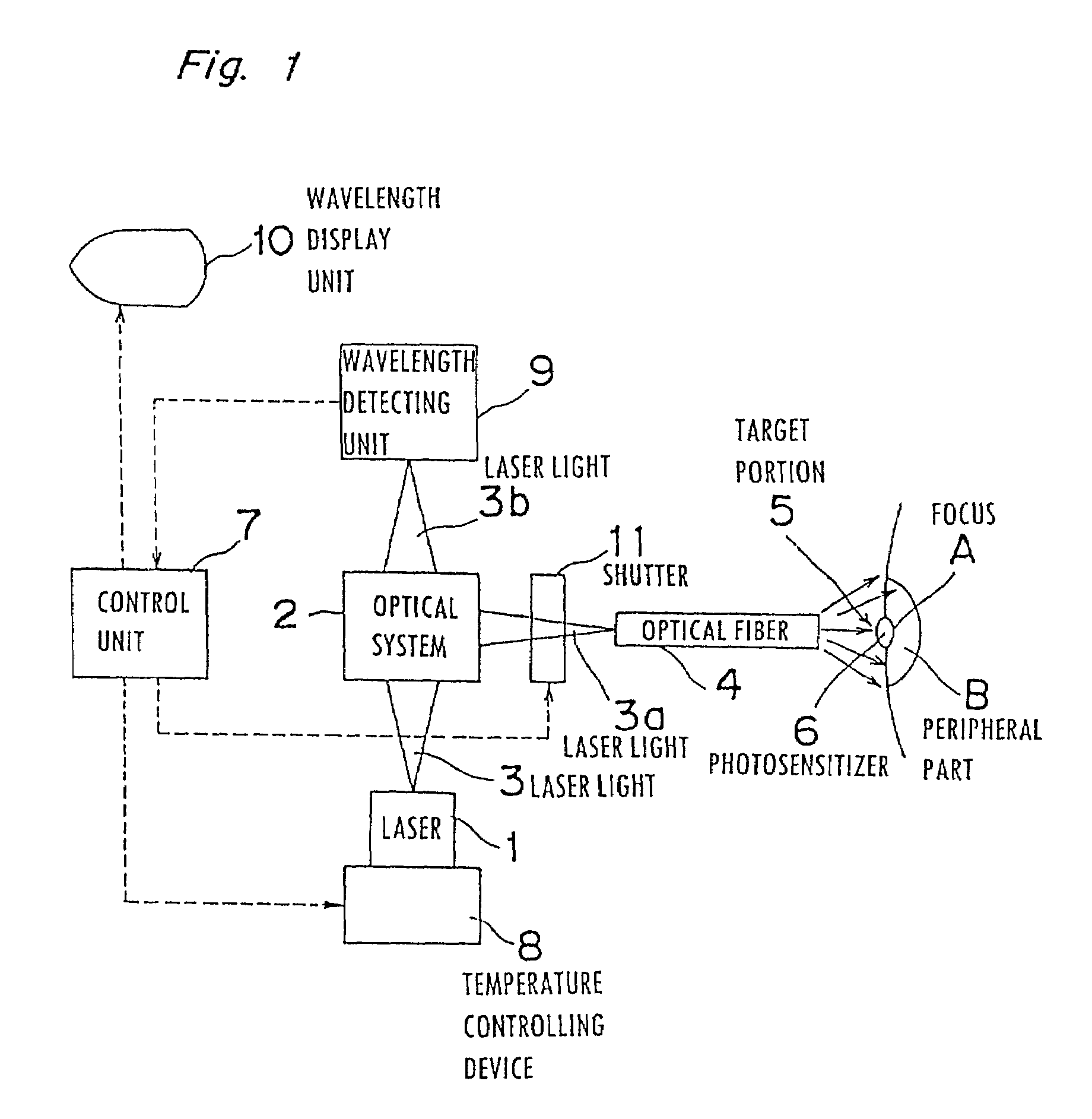
[0039]The constitution of a medical laser apparatus according to a first embodiment of the present invention is shown in FIG. 1. Referring to FIG. 1, an AlGaInP semiconductor laser 1 has an oscillating frequency 664 nm, full width at half maximum (FWHM) of ±1 nm, temperature characteristic of the oscillating wavelength 0.2 nm / deg, and operable temperature range −100 through +80° C. during driving at 0° C. An optical system 2 separates a laser light 3 projected from the semiconductor laser 1 to an irradiating laser light 3a and a wavelength detecting laser light 3b. A photosensitizer 6 is preliminarily administered in a target portion to be treated 5 including a focus A and a peripheral part B of the focus A. The other reference numerals indicate: 4 an optical fiber; 7 a control unit; 8 a temperature contr...

second embodiment

[Second Embodiment]

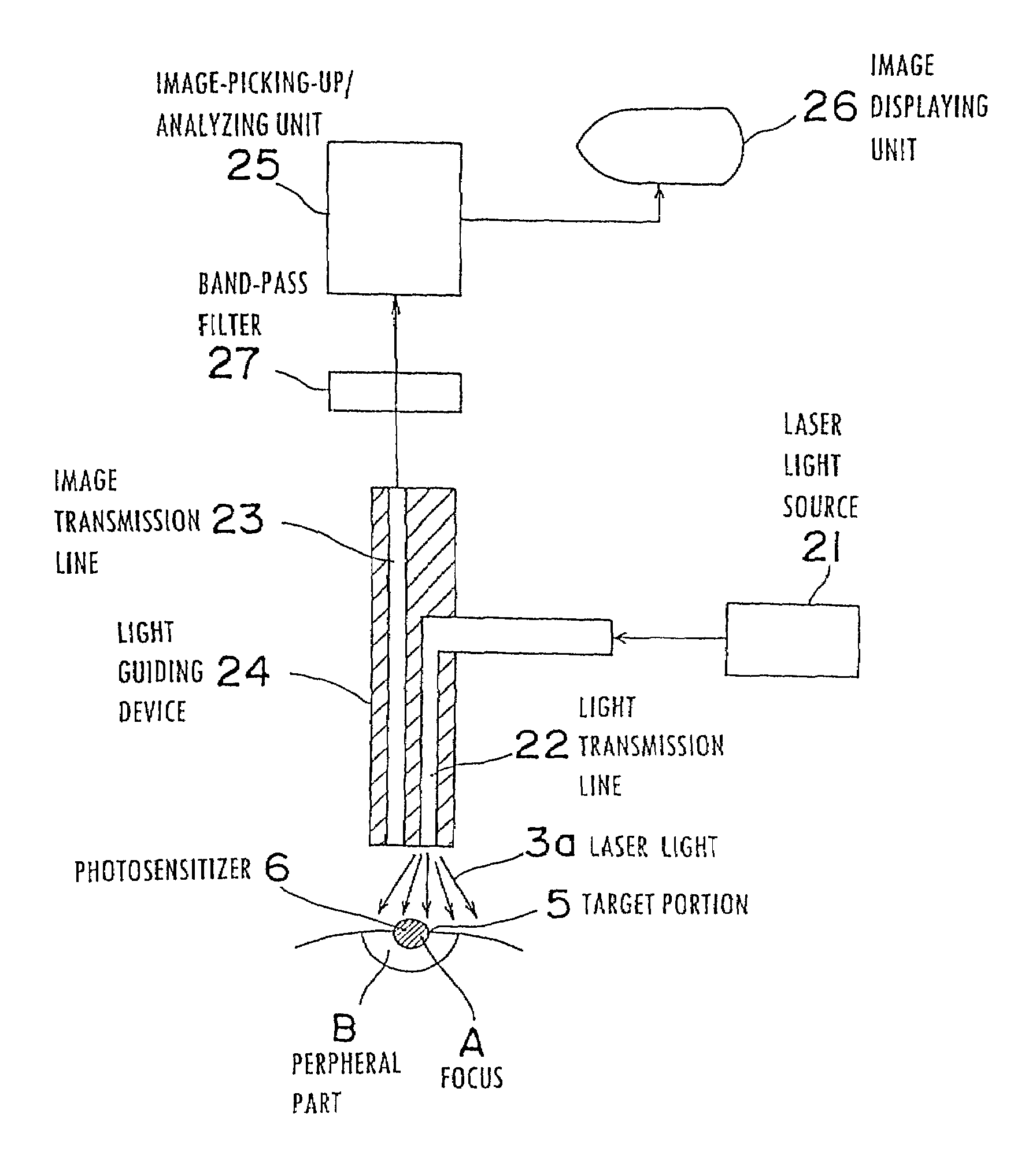
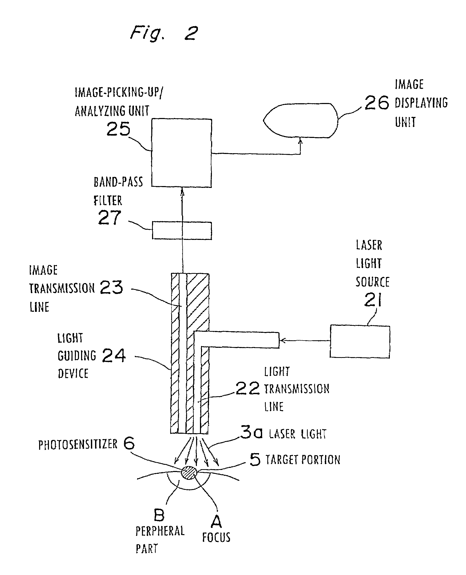
[0047]A diagnostic / treatment apparatus of cancers according to a second embodiment of the present invention will be discussed with reference to FIGS. 2 and 3.

[0048]FIG. 2 is a block diagram showing the constitution of the diagnostic / treatment apparatus of cancers according to the second embodiment of the present invention. In FIG. 2, reference numeral 21 denotes a laser light source which is the medical laser apparatus using the semiconductor laser disclosed in the foregoing first embodiment, 22 denotes a light transmission line through which the irradiating laser light 3a from the laser light source 21 is introduced to the vicinity of the focus, and 23 denotes an image transmission line through which an image of fluorescence is transmitted to observe the focus and the periphery of the focus. A light guiding device 24 incorporating the light transmission line 22 and the image transmission line 23 guides both the lines 22 and 23 to the vicinity of the focus. An ima...


PUM


Abstract

In photodynamic diagnosis and photodynamic therapy, the oscillating wavelength of laser light from a light source is fitted to a plurality of different kinds of photosensitizers and exciting conditions thereof. Moreover, diagnosis and treatment are achieved using concurrent diagnosis during treatment is realized as well. A semiconductor laser generates laser light having an oscillating wavelength which is variable and a full width at half maximum which is narrow. A light transmission line guides an irradiated laser light to the vicinity of a focus, an image transmission line observes the focus and the periphery thereof, a fluorescence light extracting device extracts only the fluorescence light emitted from a photosensitizer excited by the irradiated laser light, an image-pick-up/analyzing device picks up and analyzes an image of the extracted fluorescence light and an image display device displays the analyzing result.

Description

CROSS-REFERENCE TO RELATED APPLICATION[0001]This is a divisional application of Ser. No. 09 / 406,734, filed Sep. 28, 1999 now U.S. Pat. No. 6,383,175 which is a divisional application of Ser. No. 08 / 545,101, filed Oct. 19, 1995 (now U.S. Pat. No. 6,214,033) which is a continuation-in-part of Ser. No.08 / 174,370, filed Dec. 28, 1993, now abandoned.BACKGROUND OF THE INVENTION[0002]The present invention relates to a medical laser apparatus to be used as a light source for a diagnostic / treatment apparatus which treats a focus of a tumor such as a cancer or the like through irradiation of light to the focus. When light having a wavelength coinciding with the absorption wavelength of a photosensitizer which has an affinity to the focus and has been preliminarily accumulated in the focus is irradiated to the focus, the photosensitizer is excited, making it possible to diagnose or treat the focus. The present invention relates alike to a diagnostic / treatment apparatus using the medical laser ...

Claims


Application Information

Patent Timeline
IPC IPC(8): A61F9/008A61N5/06A61N5/067
CPCA61N5/062A61N2005/067A61N2005/0644A61B2018/00708A61B2018/00714A61B2018/00898A61N5/067
Inventor II, YOSHITERUKANEDA, AKIRAYUZU, TAKAYOSHIYAMAMOTO, TOSHIYOSHIKATO, HARUBUMIAIZAWA, KATSUO
Owner PANASONIC CORP
Why Eureka
Try Eureka