
Water and sulfur removal from combustion turbine exhaust

a technology of combustion turbine and exhaust water, which is applied in the direction of emission prevention, separation processes, lighting and heating apparatus, etc., can solve the problems of increasing difficulty, obtaining a permit to use water, and significant water cost in the process, and achieve the effect of reducing pressur

Inactive Publication Date: 2006-03-28
SIEMENS ENERGY INC
View PDF13 Cites 38 Cited by
  • Summary
  • Abstract
  • Description
  • Claims
  • Application Information

AI Technical Summary

Problems solved by technology

The cost of the water used in this process can be significant, and it is becoming increasingly difficult in some areas to obtain a permit to use water for power generation.
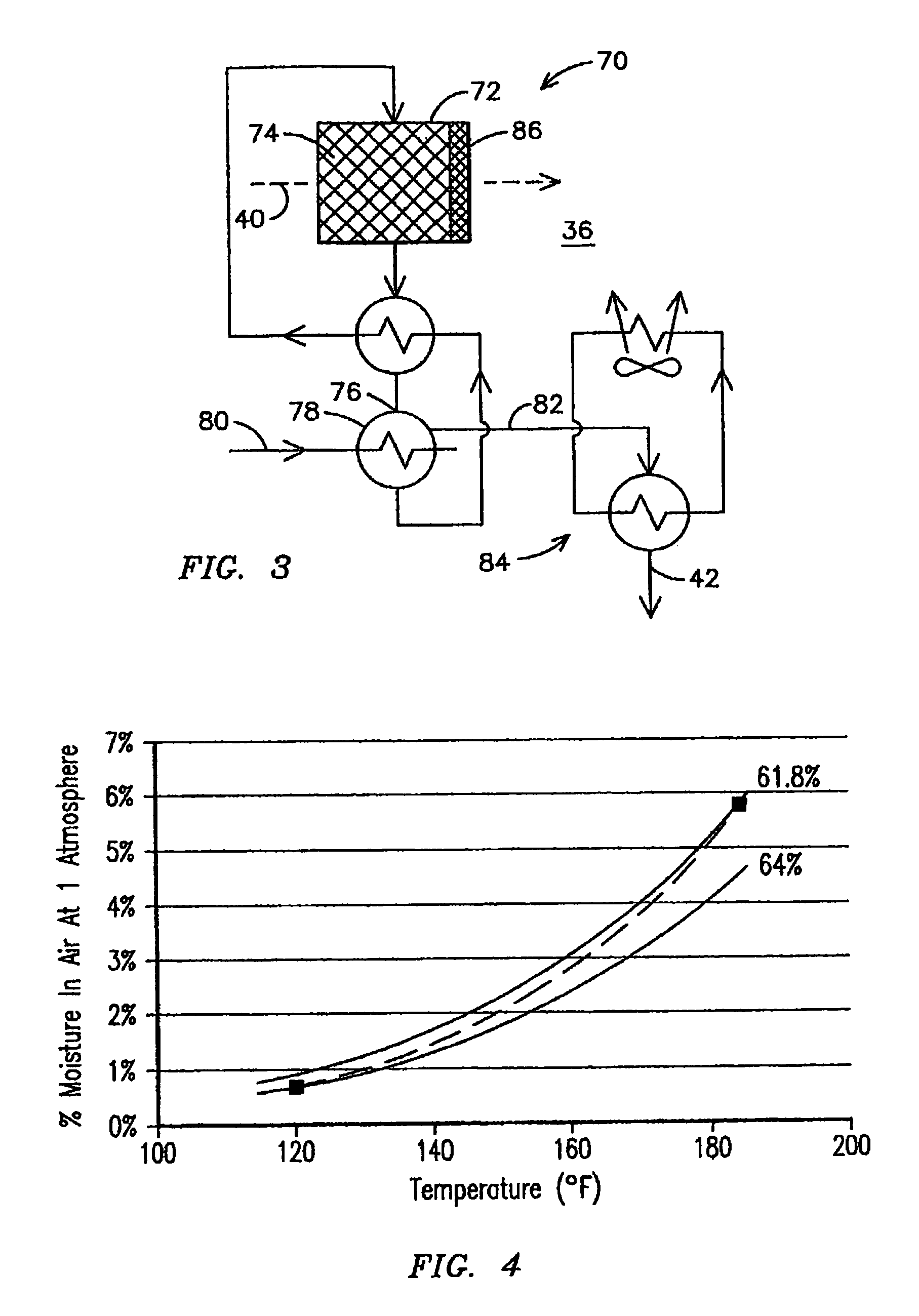
In an arid desert environment, where it is most likely that water recovery will be desired, the daytime ambient air temperature may be over 100° F. or even 110° F. and the effectiveness of water removal by an air-cooled condenser is limited.
It is known that sulfur contained in the fossil fuel burned in a combustion turbine will result in the presence of sulfuric acid in the combustion turbine exhaust stream.
Sulfuric acid is very corrosive to the carbon steels that are normally used to manufacture condenser tubes, and thus stainless steel, having a higher cost, must be used.
Seawater may be sufficiently cold to provide an adequate level of moisture removal from the combustion turbine exhaust; however, such a system would be far less efficient in a high temperature desert environment where only air-cooled condensate is available.

Method used


Image

  • Water and sulfur removal from combustion turbine exhaust
  • Water and sulfur removal from combustion turbine exhaust
  • Water and sulfur removal from combustion turbine exhaust

Examples


Embodiment Construction

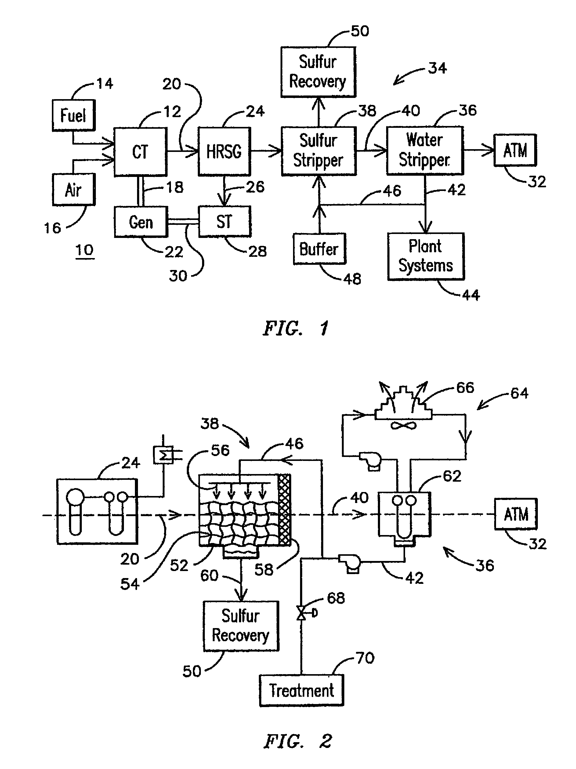
[0021]FIG. 1 is a schematic diagram illustrating an electrical generating power plant 10 utilizing a combustion turbine 12 as an engine. Combustion turbine 12, sometimes referred to as a gas turbine, incorporates components well known in the art but not illustrated in FIG. 1, such as a compressor, a combustor and a turbine. One such combustion turbine 12 is a Model 501F sold by Siemens Westinghouse Power Corporation, the assignee of the present invention.

[0022]The combustion turbine 12 combusts a flow of a fuel 14 such as natural gas, fuel oil, or other liquid or gaseous hydrocarbon fuel in a flow of air 16 to generate shaft power 18 and a stream of exhaust gas 20. The shaft power 18 is used to power an electrical generator 22 and / or other machinery. The exhaust gas 20 may be directed through a heat recovery steam generator 24 to generate steam 26. The steam 26 may be used for various applications within or outside the plant, including powering a steam turbine 28 for providing addit...


PUM


Abstract

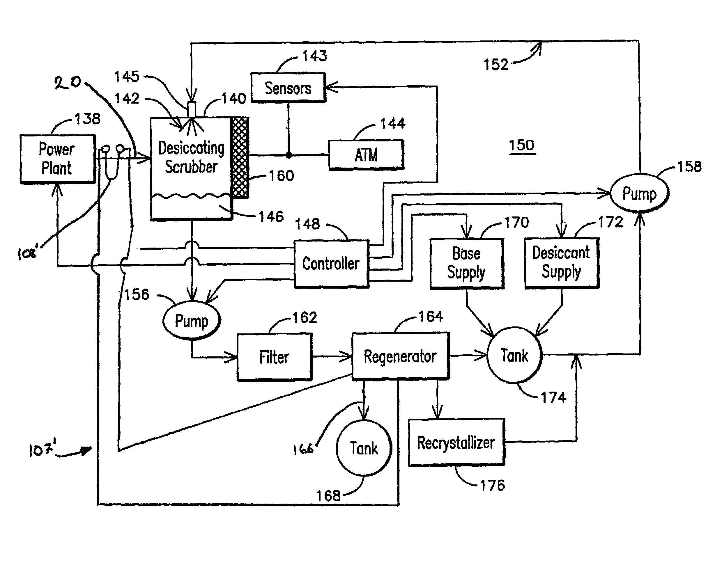
A combustion turbine power plant (10) incorporating a desiccating scrubber (140) for simultaneously removing water and sulfur from a flue gas (20) of the power plant (10). The desiccating scrubber (140) may include an inlet nozzle (145) for spraying an aqueous solution (142) containing a desiccant and a base into flue gas (20) so the aqueous solution (142) makes direct contact with flue gas (20). A filter (162) may be provided to collect sulfur compounds downstream of the desiccating scrubber (140) and a regenerator (164) may be provided for recovering water. A controller (148) may control a base supply (170) and a desiccant supply (172) to regulate the respective amounts of each introduced into the aqueous solution (142). Controller (148) may be responsive to sensors (142) measuring the water and sulfur content of flue gas (20) exhausted to atmosphere (144). The desiccating scrubber (140) may include a demister (160) to entrain carryover droplets from a sprayed aqueous solution (142).

Description

RELATED APPLICATIONS[0001]This application is a continuation in part of U.S. application Ser. No. 10 / 247,163 filed on Sep. 19, 2002, now U.S. Pat. No. 6,804,964, and titled Water Recovery From Combustion Turbine Exhaust, the specification of which is herein incorporated by reference.FIELD OF THE INVENTION[0002]This invention relates generally to the field of combustion turbine engines and more particularly, to the removal of sulfur, and the removal and recovery of water from the exhaust of a combustion turbine engine.BACKGROUND OF THE INVENTION[0003]Water or steam injection can be used for power augmentation and / or the control of nitrous oxide emissions in a combustion turbine powered electrical generating plant. The cost of the water used in this process can be significant, and it is becoming increasingly difficult in some areas to obtain a permit to use water for power generation. Accordingly, it is desirable to recover water from the exhaust stream of a combustion turbine.[0004]W...

Claims


Application Information

Patent Timeline
Patent Type & Authority Patents(United States)
IPC IPC(8): F02C7/00B01D53/14B01D53/26
CPCB01D53/1418B01D53/1468B01D53/263F02C9/28F23J15/006F23J2219/80F23J2215/20F23J2219/40F05D2270/0831
Inventor BELLOWS, JAMES C.
Owner SIEMENS ENERGY INC
Learn More