Method and apparatus for high-speed clock data recovery using low-speed circuits

a clock and low-speed technology, applied in the field of clock data recovery circuits, can solve the problems of low manufacturing yield, high processing frequency requirements, and high cost of alternative technologies, and achieve the effect of reducing the processing frequency requiremen

Inactive Publication Date: 2006-03-28
ACARD TECH CORP
View PDF19 Cites 38 Cited by
  • Summary
  • Abstract
  • Description
  • Claims
  • Application Information

AI Technical Summary

Benefits of technology

[0009]The above object has been achieved by the present invention which provides a method and an apparatus for performing clock data recovery for a high-speed serial communication system utilizing low speed digital CMOS components. The present invention reduces the processing frequency requirement of the phase detection circuit and the loop filter circuit by sampling multiple bits of data simultaneously. The present invention also provides a unique phase detection method that detects phase errors by sampling each data bit using a pair of clock signals with different phase. While one of the clock signals is set to sample the eye, i.e. the middle of the data bit pattern, the other clock signal samples the transitional area. By comparing the data bit value with the transitional bit value, phase error information is extracted. A digital filter downstream of the phase detector sifts out high frequency phase jitters from the phase error signals using a digital counter that keeps track of the phase info from the phase detector. The digital counter is segmented in a way such that the most significant portion is outputted to a phase interpolator for phase selection while the least significant portion is ignored. The phase interpolator uses the signal from the digital filter to fine-tune its clock phase output in such a way that subsequent phase errors are minimized.

Problems solved by technology

However, for high speed serial communication in the gigabit per second range, CMOS processing technology is being pushed to its limit and manufacturing yields are low while, on the other hand, alternative technologies are costly.
Although both of the above mentioned phase detection methods use digital components, the methods still have to rely on analog components to extract the phase error information.

Method used


Image

  • Method and apparatus for high-speed clock data recovery using low-speed circuits
  • Method and apparatus for high-speed clock data recovery using low-speed circuits
  • Method and apparatus for high-speed clock data recovery using low-speed circuits

Examples


Embodiment Construction

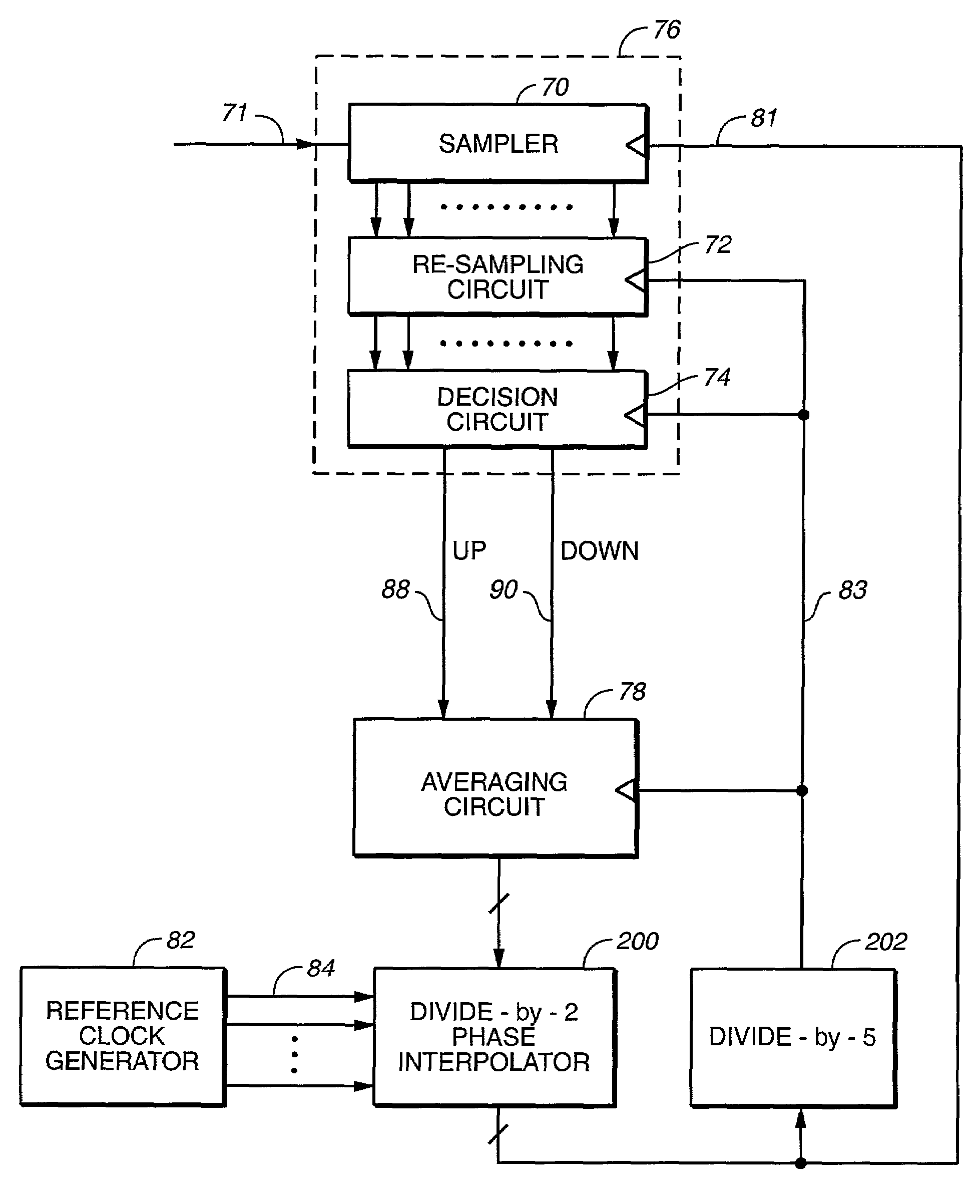
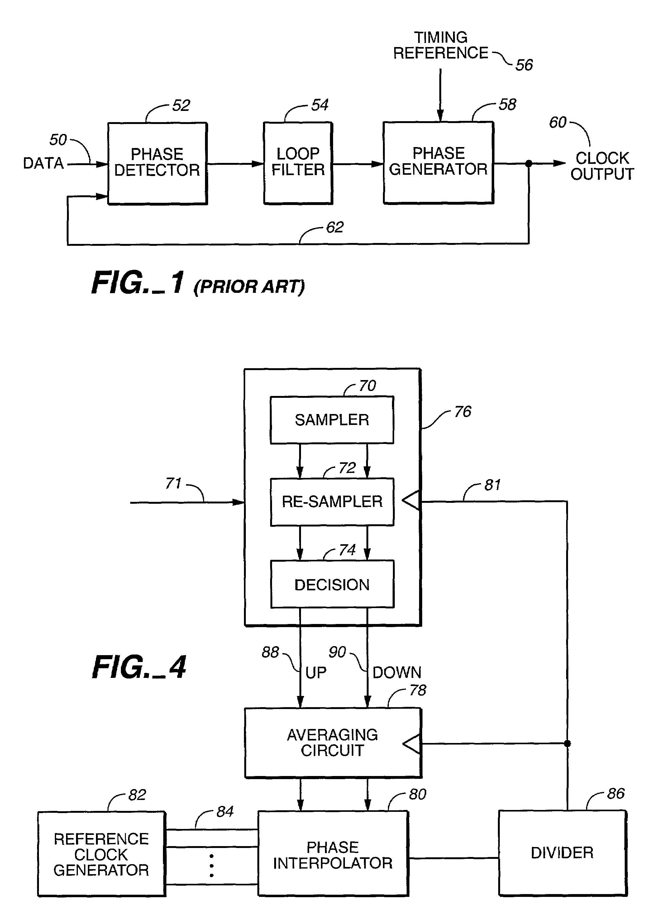
[0020]With reference to FIG. 4, sampler 70, a re-sampler 72, a decision circuit 74, an averaging circuit 78, a reference clock generator 82, and a phase interpolator 80, and a divider 86 are all seen to be electrically connected. The sampler 70, the re-sampler 72 and the decision circuit 74 as a group could be viewed as the phase detector in a conventional CDR circuit, while the reference clock generator 82 and the phase interpolator 80 as a group could be looked upon as a phase generator. The averaging circuit is the equivalent of a loop filter in a conventional CDR.

[0021]The goal of the CDR of the present invention is to maintain the primary sampling clock phase generated by the phase interpolator 80 at the eye, i.e. a point that is midway between transitions, of the each data bit. To do so, each bit of incoming data is sampled twice using a pair of clock signals with identical frequency but with a fixed phase difference that amounts to half the length of a data bit. Provided that...


PUM


Abstract

A clock data recovery (CDR) circuit that can be used for recovering data from a high-speed serial transmission using components that operate at a fraction of the data speed. The CDR consists of a phase detector, an averaging circuit and a phase interpolator. The phase detector samples each data bit at its midpoint and at its transitional region and then compares the two samples to determine whether the sampling clock, which is generated by a phase interpolator, is leading or lagging the data stream. The averaging circuit filters out the high frequency jitters in the phase detector output and then passes the filtered signals on to the phase interpolator for phase selection. The phase interpolator uses the filtered signals from the averaging circuit as a guide in the selection of an output clock phase that minimizes the phase difference between the output clock and the incoming data.

Description

TECHNICAL FIELD[0001]The present invention relates to clock data recovery circuits, and in particular, to the use of digital phase lock loop circuits for clock data recovery.BACKGROUND ART[0002]In modern communication systems, data are typically transmitted serially. These data are clocked, i.e., sent synchronously with a clock signal, which is normally not transmitted. For a receiver to recover the incoming signal accurately, it is crucial that the receiving end be able to extract a clock frequency from the incoming data signal and then use the recovered clock frequency to decipher the received signal. Phase lock loops (PLL) have been used extensively for such clock data recovery (CDR). A CDR circuit typically consists of three main components: a phase detector, a loop filter, and a phase generator. FIG. 1 shows the configuration of a typical CDR circuit. The phase detector 52 compares an incoming data signal 50 with a sampling clock signal 62 generated by the phase generator 58 to...

Claims


Application Information

Patent Timeline
Patent Type & Authority Patents(United States)
IPC IPC(8): H04L7/00H03D3/24H03L7/06H04L7/033
CPCH04L7/0337H04L7/0025
Inventor WANG, DAVID Y.SHYU, JYN-BANGCHENG, YU-CHI
Owner ACARD TECH CORP
Why Eureka
Try Eureka