Vehicle accelerator pedal device

a technology of accelerator pedal and pedal, which is applied in the direction of mechanical control devices, electrical control, instruments, etc., can solve the problems of difficult to precisely adjust the mounting position of the kickdown switch, the difference between the timing, and the delicate settings of the accelerator pedal operation and vehicle operability, so as to reduce the reaction force, reduce the capacity of the accelerator pedal, and reduce the cost and power consumption of the accelerator pedal device

Active Publication Date: 2006-04-04
HONDA MOTOR CO LTD
View PDF10 Cites 18 Cited by
  • Summary
  • Abstract
  • Description
  • Claims
  • Application Information

AI Technical Summary

Benefits of technology

[0017]Further, in the present invention, the accelerator pedal device preferably mechanically produces part of the reaction force provided to the accelerator pedal with a return spring. That is, the return spring allows the red...

Problems solved by technology

Therefore in the adjustment of pedal reaction force to a predetermined value at a desired degree of throttle opening, a difference between the timing of the throttle opening and the timing of the pedal reaction force can occur, making delicate settings on the accelerator pedal oper...

Method used


Image

  • Vehicle accelerator pedal device
  • Vehicle accelerator pedal device
  • Vehicle accelerator pedal device

Examples


Embodiment Construction

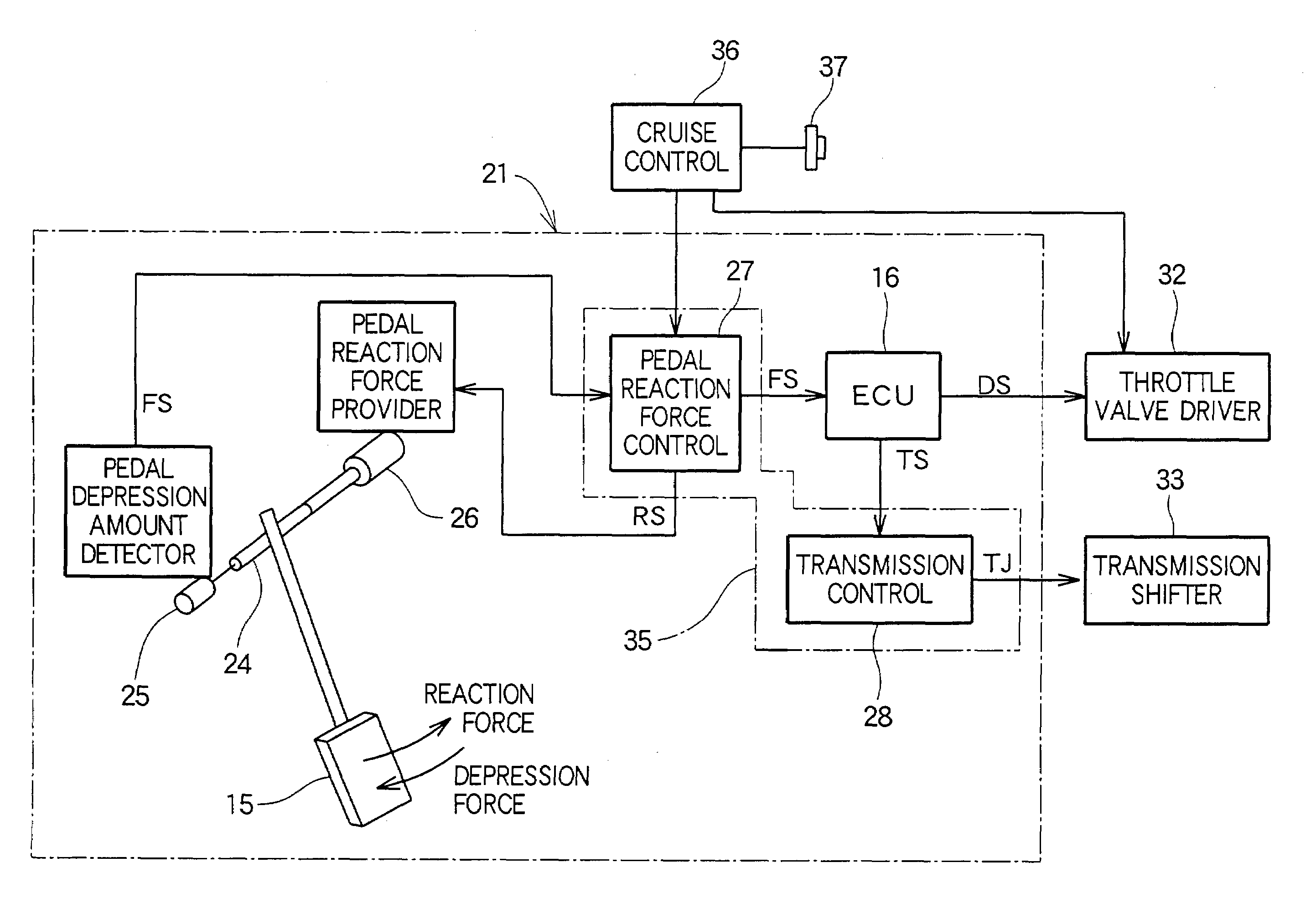
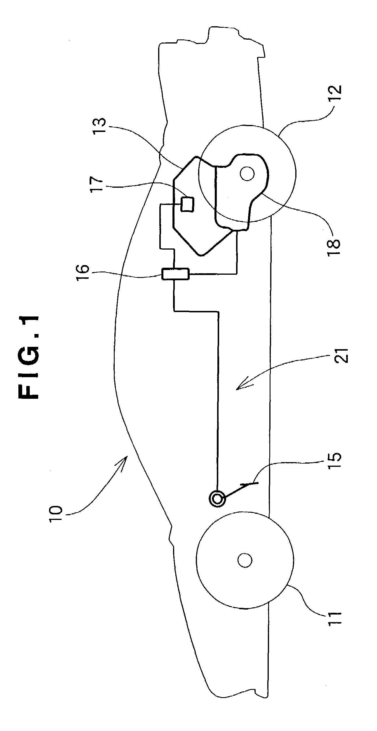
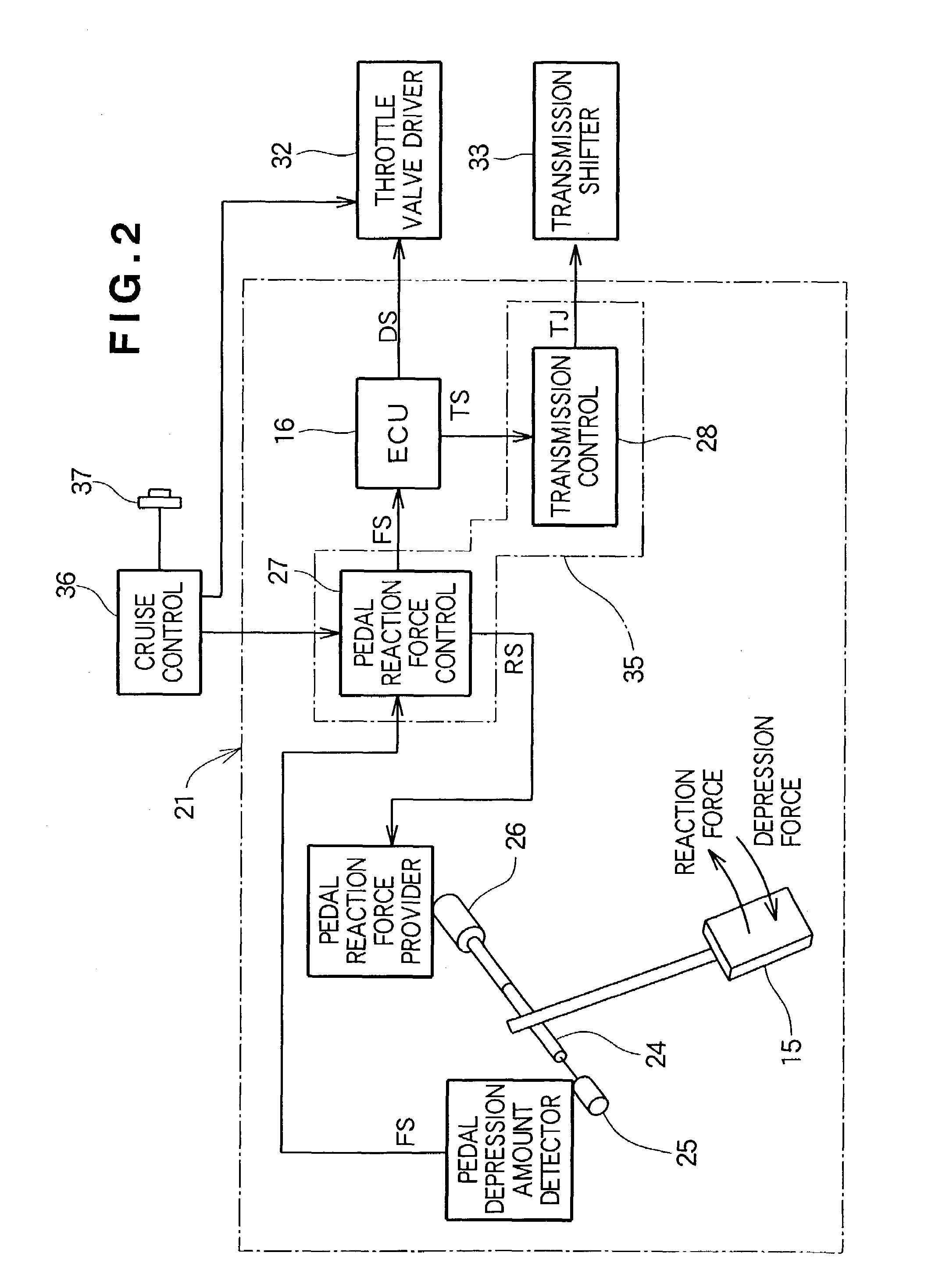
[0029]A vehicle 10 in the present embodiment shown in FIG. 1 is a midship vehicle with an engine 13 arranged closer to rear wheels 12 between front wheels 11 and the rear wheels 12. An accelerator pedal 15 is arranged in a front lower position of a driver seat. The accelerator pedal 15 is operated to change the degree of opening of a throttle valve (not shown) (that is, throttle opening) of a throttle body 17 provided at an upper portion of the engine 13, controlling the engine output. The operation of the accelerator pedal 15 also provides the control of the gear change of an automatic transmission 18 connected to the engine 13 under a command from an ECU 16.

[0030]An accelerator pedal is generally mechanically connected to a throttle valve via a throttle cable or the like. The vehicle 10 adopts a DBW (drive by wire) structure in which the accelerator pedal 15 is connected by wire or electrical wiring to the throttle body 17 (specifically, a throttle valve driving means (to be descr...


PUM


Abstract

An accelerator pedal device includes a pedal reaction force providing device for providing a reaction force to an accelerator pedal according to an amount of depression of the accelerator pedal operated by a driver. The reaction force to be provided from the pedal reaction force providing device to the pedal is controlled based on the depression amount of the accelerator pedal. This reaction force control allows precise agreement between throttle opening timing and pedal reaction force timing to produce a predetermined pedal reaction force at a desired degree of throttle opening.

Description

FIELD OF THE INVENTION[0001]The present invention relates to vehicle accelerator pedal devices which allow precise agreement between the timing of a desired degree of throttle opening and the timing of the production of a predetermined pedal reaction force, and allow precise agreement between kickdown and the production of reaction force at accelerator pedals.BACKGROUND OF THE INVENTION[0002]In vehicles, levers and pedals, for example, are input devices to be operated by drivers. When they are operated, certain amounts of reaction forces are generally received at hands and feet. There are, however, arts of positively producing the reaction forces in accordance with the operations of levers and pedals, that is, allowing the levers and pedals to serve as not only input devices but also output devices. Such devices are called haptic devices.[0003]Such a device is disclosed, for example, in Japanese Patent Laid-Open Publication No. 2001-105926 entitled “Operating Device for Vehicle.” Th...

Claims


Application Information

Patent Timeline
IPC IPC(8): F16H59/48B60K31/00G06F17/00G06F19/00G06F7/00B60K26/02F02D11/10F16H59/18G05G1/30
CPCB60K31/00F02D11/105G05G1/30G05G5/03B60K26/021B60W2540/10F02D41/0225F02D41/023Y10T477/65F02D2200/0404F02D2200/602F16H59/18Y10T477/692F02D2011/102
Inventor YONE, SHINICHI
Owner HONDA MOTOR CO LTD
Why Eureka
Try Eureka