Multiplanar EMI shielding gasket and method of making

a shielding gasket and multi-planar technology, applied in the field of emi shielding gaskets, can solve the problems of reducing the efficiency of the ground conduction path, affecting the electrical efficiency of the ground, and affecting the use of raw materials, so as to reduce the cost of raw materials used, widen the range of applications, and facilitate the use of cornering.

Active Publication Date: 2006-04-04
PARKER INTANGIBLES LLC
View PDF12 Cites 11 Cited by
  • Summary
  • Abstract
  • Description
  • Claims
  • Application Information

AI Technical Summary

Benefits of technology

[0023]The construction of the present invention provides flexibility and corner-ability that is unmatched by conventional products. It is the absence of a stiff, metallized woven fabric as well as the absence of layers of coatings or adhesives used to adhere the foam to the conductive fabric that allows the present invention to closely contact the electronic enclosure in order to give as close to perfect an EMI seal as possible; a critical characteristic needed for future high clock speeds with ultra-fine electric wave amplitude.
[0024]Further, the simplicity of manufacturing and the lower cost of the raw materials used provides important savings in the cost of the finished product. In addition, the simplified manufacturing process provides a user with a much wider or broader range of applications.

Problems solved by technology

The gaps between the panels, hatches, etc., and a housing provide an undesired opportunity for EMI / RFI to pass through the shield.
The gaps also interfere with electrical currents running along the surfaces of the housing from EMI / RFI energy, which is absorbed and is being conducted to ground.
The gaps reduce the efficiency of the ground conduction path and may even result in the shield becoming a secondary source of EMI / RFI leakage.
Unfortunately, there are inevitable compromises between the ability of a gasket to smoothly and thoroughly engage and conform to the surface of the housing adjacent the gaps, the conductive capacity of the gasket, the ease of mounting the gasket, the ability of the gasket to withstand abrasive wear and tear as well as repeated compression and relaxation, and the cost of manufacturing the gasket.
A disadvantage of the Clupper device is that the metallization process must be carefully controlled in order to sufficiently coat the gasket with metal throughout the foam substrate to provide proper through-conductivity, yet not overly coat with metal such that the metallized foam becomes difficult to compress and / or insufficiently resilient.
A disadvantage of the Laird conductive foam is that it is designed for non-dynamic, low stress areas such as input / output shielding as well as other standard connector configurations.
A disadvantage of this device is that the metal-plated coating can break with repeated compression and relaxation causing a degradation in the through conductivity of the gasket.
The metallic-plated conductive foams of the above disclosures are not re-usable in dynamic applications because the plated metal surfaces that have been laid within the cells of the foam are rigid.

Method used


Image

  • Multiplanar EMI shielding gasket and method of making
  • Multiplanar EMI shielding gasket and method of making
  • Multiplanar EMI shielding gasket and method of making

Examples


second embodiment

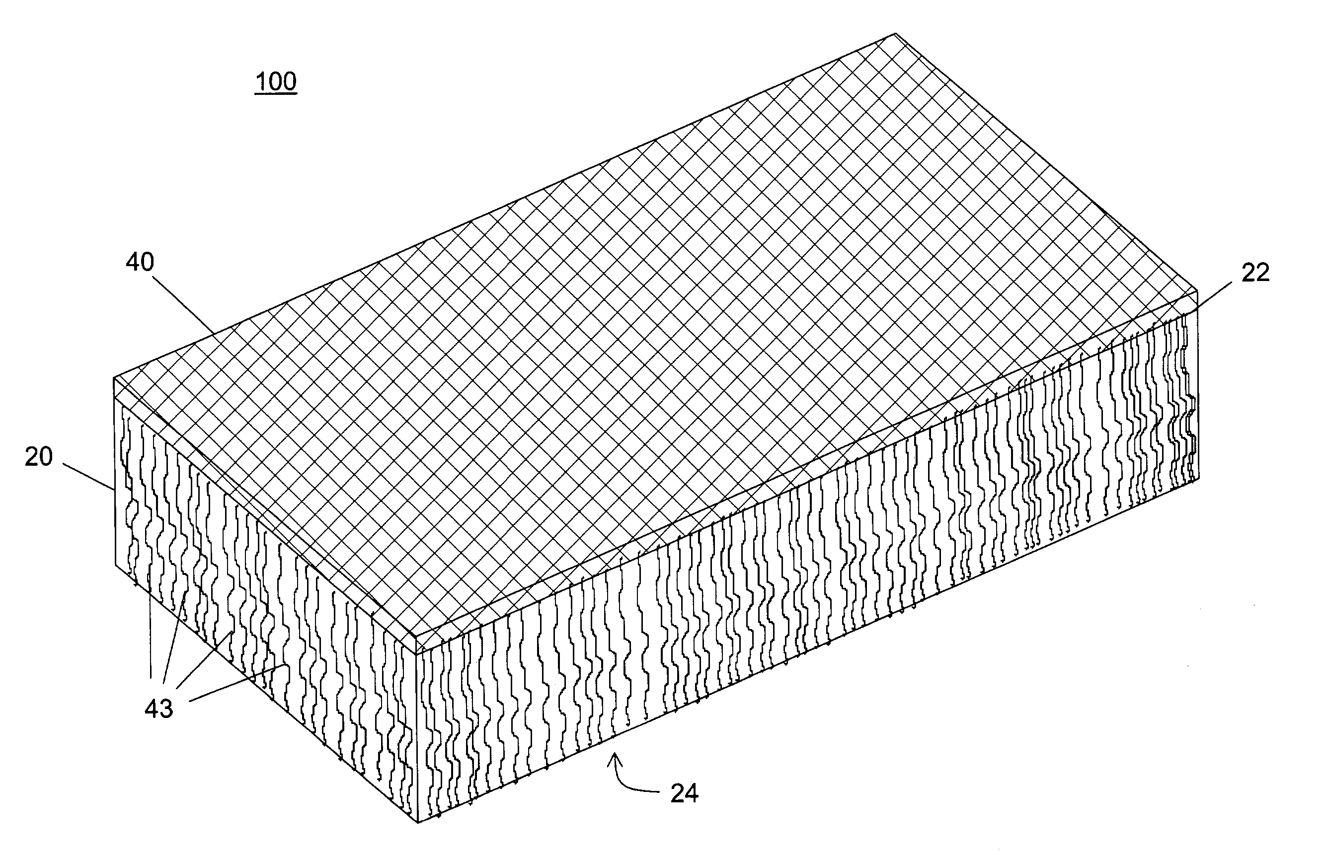
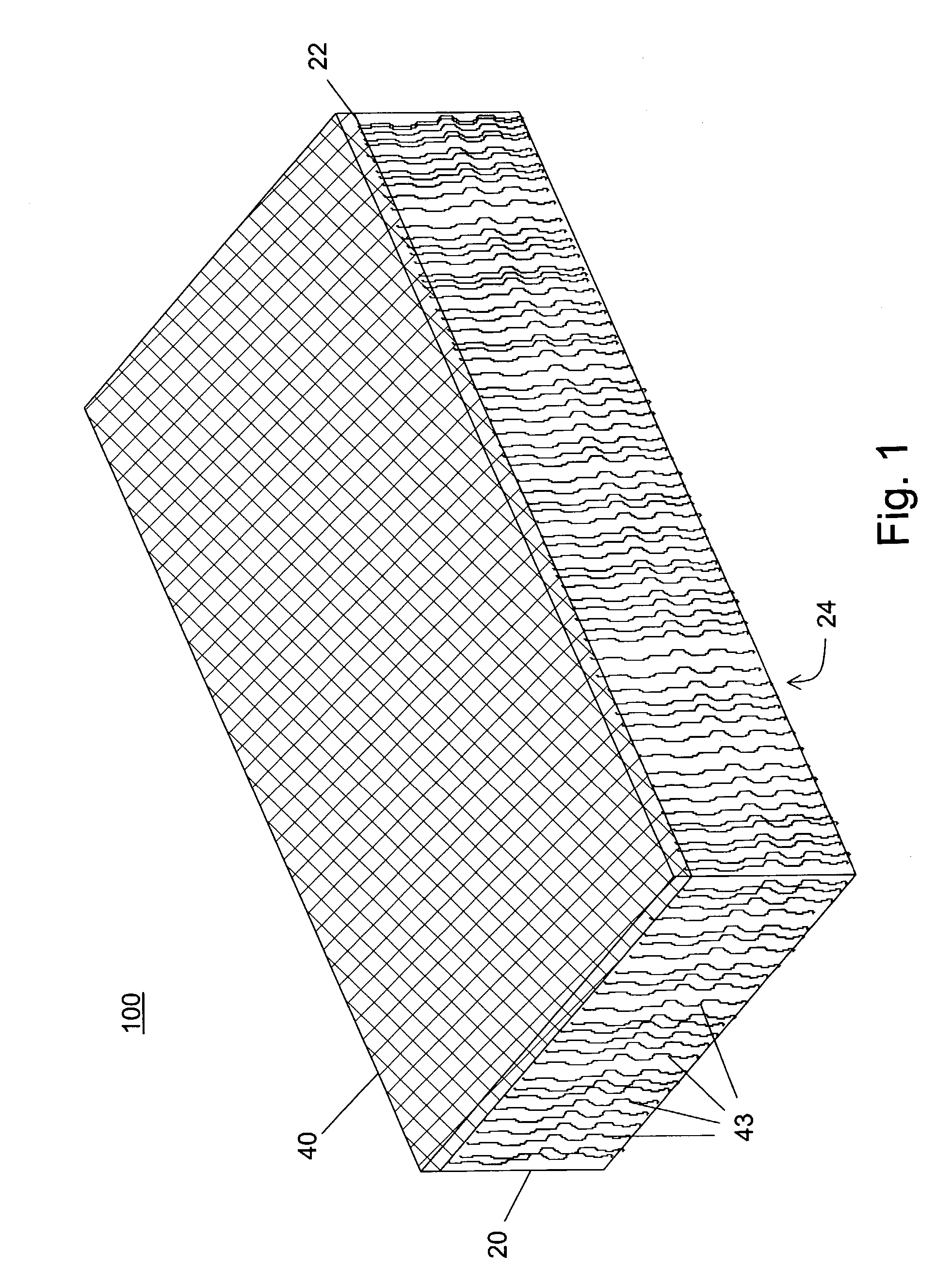
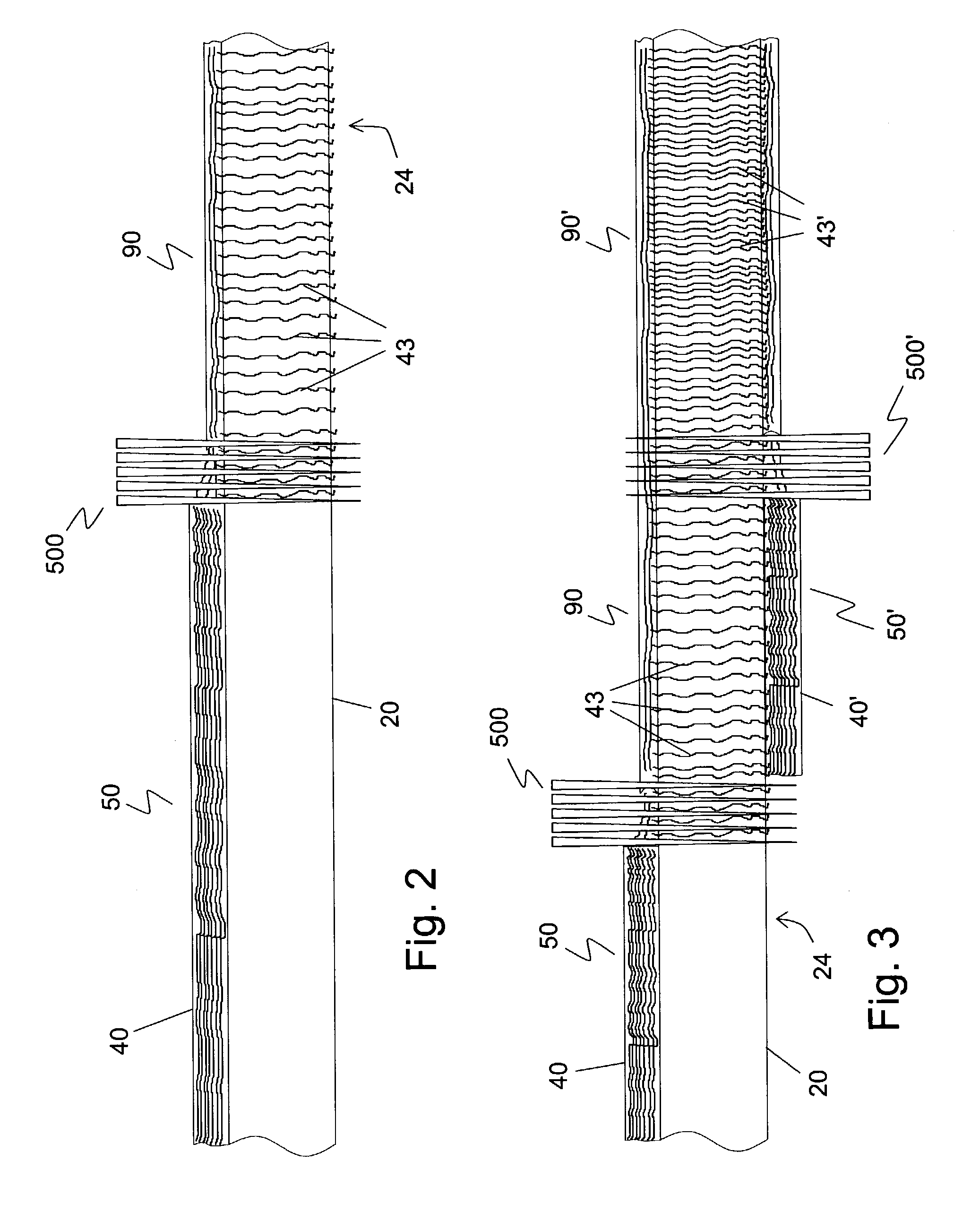
[0036]Turning now to FIG. 3, there is illustrated a cross-sectional view of the needleloom process making EMI gasket material 100. As described above, conductive fiber web 40 is brought into a layered relationship with foam core 20 forming a multiplanar assembly 50. Multiplanar assembly 50 is then subjected to a needleloom 500 that processes the multiplanar assembly 50. Needleloom 500 intersperses individual fibers 43 of web 40 from web 40 through foam core 20 so that a plurality of individual fibers 43 protrude out of bottom surface 24. The needleloom process interlocks, or binds, fiber web 40 to foam core 20 forming multiplanar core 90. A second conductive fiber web 40′ is then brought into a layered relationship with foam core 20 at bottom surface 24 forming a multiplanar assembly 50′ composed of multiplanar core 90 and second conductive fiber web 40′. Multiplanar assembly 50′ is then subjected to a second needleloom 500′ that processes the multiplanar assembly 50′. Needleloom 50...

third embodiment

[0037]In instances where the thickness of foam core 20 is too thin such as, for example, less than five millimeters in thickness, the gasket material 100 may lack a certain needed firmness, stiffness or rigidity. FIG. 4 is a cross-sectional view of the needleloom process making EMI gasket material 100. A non-conductive, stiffening fabric 30 is brought into a layered relationship between conductive fiber web 40 and foam core 20 forming a multiplanar assembly 150. Multiplanar assembly 150 is then subjected to a needleloom 500 that processes the multiplanar assembly 150. Needleloom 500 intersperses individual fibers 43 of web 40 from web 40 through stiffening fabric 30 and foam core 20 so that a plurality of individual fibers 43 protrude out of bottom surface 24. The needleloom process interlocks, or binds, fiber web 40 to stiffening fabric 30 and foam core 20 forming multiplanar core 190.

[0038]Stiffening fabric 30 is preferably a web of nonconductive fibers having a blend of about 4 t...


PUM

PropertyMeasurementUnit
softening pointaaaaaaaaaa
thicknessaaaaaaaaaa
sizeaaaaaaaaaa

Abstract

A multiplanar, conductive gasket material having a foam core, a conductive web layer comprising a blended mixture of conductive fibers and nonconductive fibers, and a plurality of blended mixture fibers interspersed through the foam core. The blended mixture fibers are heat set within the gasket material.

Description

BACKGROUND OF THE INVENTION[0001]1. Field of the Invention[0002]The present invention relates generally to an EMI shielding gasket. Particularly, the present invention relates to an EMI shielding gasket having electrical conductivity through the gasket.[0003]2. Description of the Prior Art[0004]EMI shielding gaskets are used to electrically seal gaps in metallic enclosures that encompass electronic components. The gaps between the panels, hatches, etc., and a housing provide an undesired opportunity for EMI / RFI to pass through the shield. The gaps also interfere with electrical currents running along the surfaces of the housing from EMI / RFI energy, which is absorbed and is being conducted to ground. The gaps reduce the efficiency of the ground conduction path and may even result in the shield becoming a secondary source of EMI / RFI leakage.[0005]Various configurations of gaskets have been developed over the years to close the gaps to effect the least possible disturbance of the groun...

Claims


Application Information

Patent Timeline
Patent Type & Authority Patents(United States)
IPC IPC(8): B32B3/26B32B3/00H05K9/00
CPCH05K9/0015Y10T29/49151Y10T29/49211Y10T29/49204Y10T29/49162Y10T442/637Y10T428/249981Y10T442/3358Y10T428/249955Y10T428/249953Y10T442/696Y10T442/697Y10T428/24996Y10T428/24999Y10T442/651Y10T442/647Y10T428/249958H05K9/00
Inventor KAPLO, JOSEPH J.
Owner PARKER INTANGIBLES LLC
Why Eureka
Try Eureka