
Ballast apparatus and ballasting method of high intensity discharge lamp

a technology of ballast apparatus and ballast, which is applied in the direction of electric variable regulation, process and machine control, instruments, etc., can solve the problems of increasing the size of the transformer, preventing implementation, and breaking in a hot condition

Active Publication Date: 2006-04-04
MITSUBISHI ELECTRIC CORP
View PDF8 Cites 15 Cited by
  • Summary
  • Abstract
  • Description
  • Claims
  • Application Information

AI Technical Summary

Benefits of technology

The present invention provides a compact and inexpensive ballast apparatus and method for a high intensity discharge lamp that can turn on normally using a DC-AC one-step-boost high frequency ballast system. The apparatus includes a plurality of power supplies and switching elements, which are controlled to generate an AC voltage higher in voltage and frequency than the primary side voltage of the transformer. This allows for sufficient energy to be supplied to the HID lamp during the discharge developing period, simplifying the circuit configuration and reducing its size and cost. The method includes driving the high intensity discharge lamp by a driving voltage undergoing frequency modulation with a center frequency in a range from 80 kHz to 120 kHz, and controlling the duty factor of waveforms for driving the switching elements to achieve a stable turn-on of the HID lamp.

Problems solved by technology

To apply the circuit scheme to the ballast apparatus of the metal halide lamp, the singular requirements of the metal halide lamp must be met, which prevents the implementation thereof.
Furthermore, to satisfy the requirements to start the metal halide lamp, it is necessary to generate a high voltage pulse of about 20 kV or more across the lamp to cause breakdown in a hot condition during a discharge start period.
This increases the size of the transformer, hampering the reduction in size and cost of the high intensity discharge lamp ballast apparatus.

Method used


Image

  • Ballast apparatus and ballasting method of high intensity discharge lamp
  • Ballast apparatus and ballasting method of high intensity discharge lamp
  • Ballast apparatus and ballasting method of high intensity discharge lamp

Examples


embodiment 1

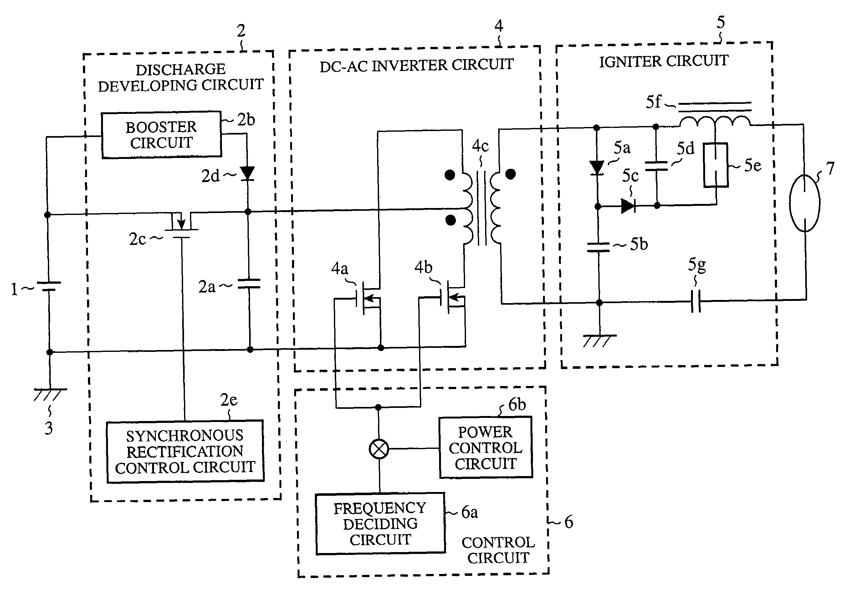
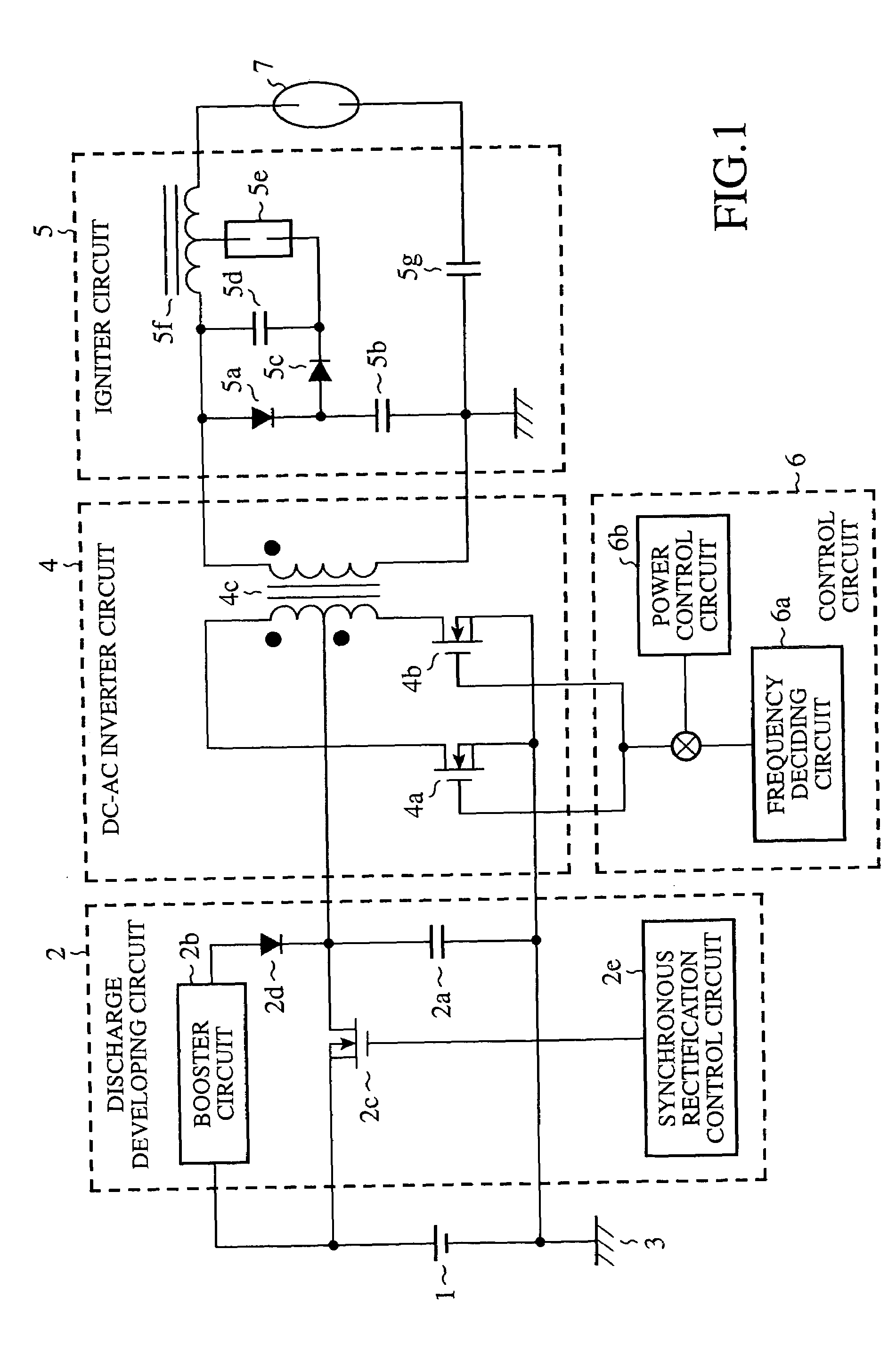
[0045]The embodiment 1 will be described with reference to FIGS. 1–7. FIG. 1 is a circuit diagram showing the embodiment 1 of the high intensity discharge lamp ballast apparatus in accordance with the present invention.

[0046]As shown in FIG. 1, the high intensity discharge lamp ballast apparatus includes a DC power supply 1, a discharge developing circuit 2, a DC-AC inverter circuit 4, an igniter circuit 5, and a control circuit 6, and turns on the metal halide lamp 7.

[0047]The DC power supply 1 generates a 12 V DC voltage, and supplies it to the discharge developing circuit 2. The minus potential side is connected to a ground line 3.

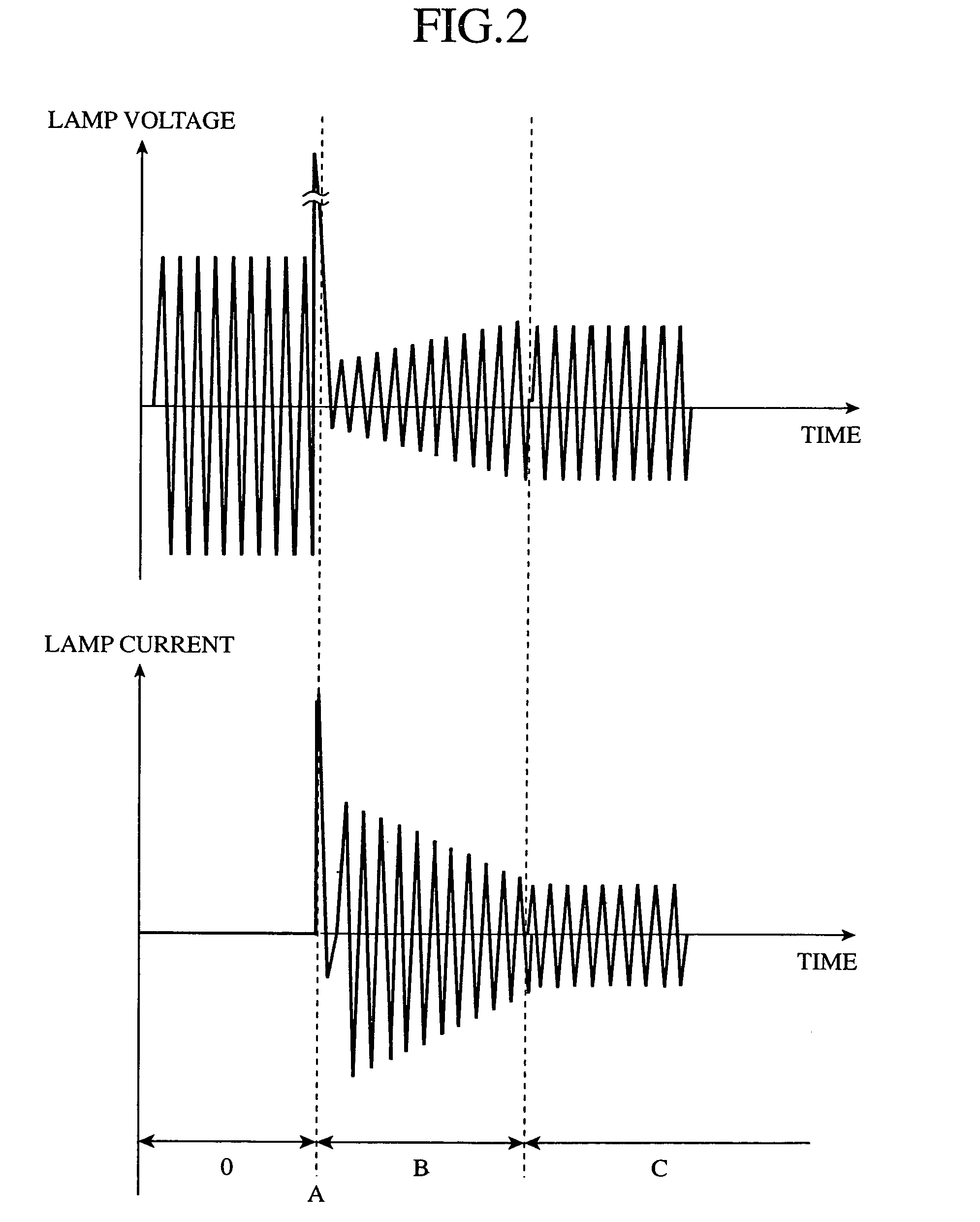
[0048]The discharge developing circuit 2 is provided to supply the HID lamp with sufficient energy during the discharge developing period. It includes a discharge developing capacitor 2a, a booster circuit 2b, a synchronous rectification switching element 2c, a reverse blocking diode 2d, and a synchronous rectification control circuit 2e. The booster ci...

embodiment 2

[0086]Next, the embodiment 2 of the high intensity discharge lamp ballast apparatus will be described with reference to FIG. 8. The embodiment 2 relates to a ballast method for reducing the capacity Ca of the discharge developing capacitor 2a. FIG. 8 illustrates the voltage across the gap switch 5e on the secondary side of FIG. 1, the voltage across the discharge developing capacitor 2a on the primary side, and the signal fed to the inverter. In the following description, FIGS. 1–7 and their description in the embodiment 1 will be referred to where appropriate.

[0087]The discharge developing capacitor 2a must store, in addition to the energy supplied to the lamp during the discharge developing period, the energy necessary for increasing up to the voltage enabling the gap switch 5e to turn on. The energy Wg required to increase up to the turn-on voltage Vg of the gap switch 5e is given by the following expression.

Wg=½·Cg·Vg2  (1)

where Cg is the capacity of the gap switch activating ca...


PUM


Abstract

A ballast for a vehicle metal halide lamp is simplified using a DC-AC one-step-boost high frequency ballast system. To satisfy requirements specific to a metal halide lamp, a discharge developing capacitor is installed on a primary side of a transformer in parallel with a DC power supply, ensuring discharge development after a breakdown. To reduce the size and increase the operating voltage of the transformer, a booster circuit and voltage-doubler circuit are installed on the primary side and secondary side of the transformer, respectively. To reduce the size of the transformer and achieve a stable discharge, the ballast frequency is swept within a range between the specified minimum frequency and maximum frequency so that the center frequency is from 80 kHz to 120 kHz, and the same frequency is unsustained for more than 10 msec.

Description

BACKGROUND OF THE INVENTION[0001]1. Field of the Invention[0002]The present invention relates to a ballast apparatus and ballasting method of a high intensity discharge lamp, such as a metal halide lamp, used as the light source of the headlights of an automobile or the like.[0003]2. Description of Related Art[0004]Recently, metal halide lamps have been used as the headlights of an automobile instead of halogen lamps. The metal halide lamp, one of the HID (High Intensity Discharge) lamp, is characterized by its high luminous efficiency, high color temperature and long life compared with the halogen lamp.[0005]The arc tube of the metal halide lamp contains metal halides which are mixtures of some metals such as sodium and scandium with halogen such as iodine, high pressure xenon serving as a starting gas, and mercury. The metal halide lamp starts emitting light as follows. First, it starts discharge of the xenon in a gaseous condition at room temperature, followed by arc discharge of...

Claims


Application Information

Patent Timeline
Patent Type & Authority Patents(United States)
IPC IPC(8): H05B37/02H05B41/24H05B41/18H05B41/282H05B41/288H05B41/292H05B41/38
CPCH05B41/2881H05B41/2886H05B41/2928H05B41/388H05B41/2887Y02B20/202Y02B20/00
Inventor HARADA, SHIGEKIIZUMI, KIKUOURAKABE, TAKAHIROSUZUKI, AKIHIRONIWATA, AKIHIKOOHSAWA, TAKASHI
Owner MITSUBISHI ELECTRIC CORP
Learn More