Method of extracting locations of nucleic acid array features

a nucleic acid array and feature extraction technology, applied in biochemistry apparatus and processes, instruments, image enhancement, etc., can solve problems such as systematic errors in the deposition system

Inactive Publication Date: 2006-04-11
AGILENT TECH INC
View PDF18 Cites 16 Cited by
  • Summary
  • Abstract
  • Description
  • Claims
  • Application Information

AI Technical Summary

Problems solved by technology

Ideal feature locations (the locations in which features would be deposited if no measurable errors existed in the deposition system) are determined, and a source of systematic error in the deposition system is also located.

Method used


Image

  • Method of extracting locations of nucleic acid array features
  • Method of extracting locations of nucleic acid array features
  • Method of extracting locations of nucleic acid array features

Examples


Embodiment Construction

[0017]While the present invention is described herein with reference to a particular embodiment of sensing feature positions in DNA arrays for genetic sequencing, it will be understood by those skilled in the art that the methods of the invention can be applied to many other image analysis applications. In particular, many other chemical assays (e.g., immunodiagnostic assays) exist for measurement of the relative binding of an analyte species to a number of substrate regions; the methods and systems of the invention may easily be used for such assays. Broader applications may include such diverse systems as machine vision systems for recognition of objects, systems for doping a substrate to construct integrated circuits, and automatic systems for astronomical observation.

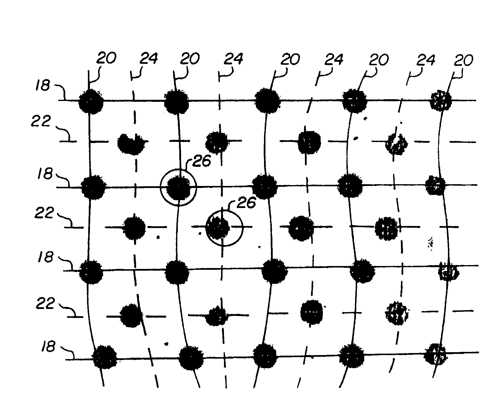
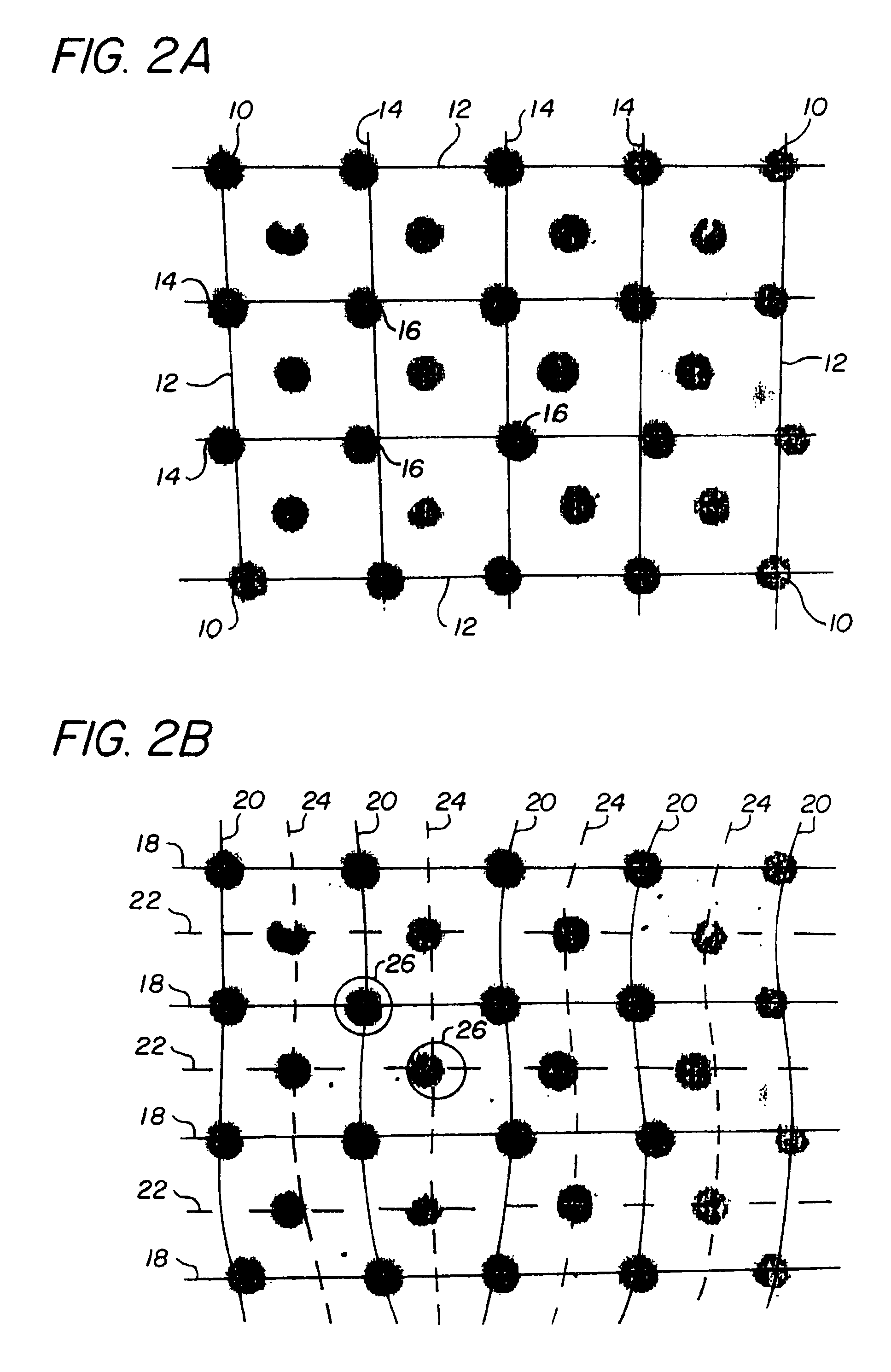
[0018]The invention comprises methods of compensating for identified sources of systematic error in deposition and / or scanning of feature arrays. Examples of sources of systematic error include registration error in...


PUM

PropertyMeasurementUnit
distanceaaaaaaaaaa
thresholdaaaaaaaaaa
areaaaaaaaaaaa

Abstract

Methods for correcting systematic errors in the measured position of deposited features of a nucleic acid array on a substrate. Systematic errors are modeled by an algorithmic model based on measuring the positions (and possibly other properties) of a subset of the features, and a model is constructed for predicting deviations in feature position from an ideal grid. Deviations arising in the deposition process, the scanning process, or both may be corrected.

Description

RELATED U.S. APPLICATION DATA[0001]This application is a continuation of U.S. application Ser. No. 09 / 435,462 filed on Nov. 5, 1999 now abandoned.FIELD OF THE INVENTION[0002]This application pertains to methods and apparatus for determining locations of features in a surface array, and to methods and apparatus for compensating for systematic errors in the determination of feature positions.BACKGROUND OF THE INVENTION[0003]The rapid pace of genetic research has required the development of new research tools to efficiently determine both genotype and gene expression levels in cellular organisms. “Gene chips” which contain arrays of short DNA or RNA chains in an array of sequences bound to a substrate (usually glass) are now commercially available. The chip is indexed so that the particular sequence bound in any area is known (or, in the case of cDNA, at least the cell line is known); a region having a homogeneous composition is referred to as a “feature.” The chips can be incubated wi...

Claims


Application Information

Patent Timeline
Patent Type & Authority Patents(United States)
IPC IPC(8): G06K9/00C12Q1/68G06T7/00G16B25/00G16B40/00
CPCC12Q1/6837G06F19/20G06K9/3216G06T7/0042B01J2219/00378B01J2219/00608B01J2219/00612B01J2219/00659B01J2219/00693B01J2219/00704G06T2207/30072B01J2219/00725G06F19/24B01J2219/00722G06T7/73G16B25/00G16B40/00G06V10/245
Inventor CATTELL, HERBERT F.DORSEL, ANDREAS N.SADLER, JOHN W.SAMPAS, NICHOLAS M.
Owner AGILENT TECH INC
Why Eureka
Try Eureka