Apparatus for controlling engine rotation stop by estimating kinetic energy and stop position

a technology of kinetic energy and engine, which is applied in the direction of electrical control, lighting and heating apparatus, instruments, etc., can solve the problems of difficult to improve a starting operation and exhaust emission at the start, the crank angle at the time of engine rotation stop cannot be exactly detected, and the accuracy of estimation is difficult to achieve. , to achieve the effect of improving the starting quality and exhaust emission, and reducing the variation of the engine rotation stop position

Inactive Publication Date: 2006-04-11
DENSO CORP
View PDF5 Cites 66 Cited by
  • Summary
  • Abstract
  • Description
  • Claims
  • Application Information

AI Technical Summary

Benefits of technology

[0014]It is a first object of the present invention to enable reducing variation in engine rotation stop position and accurately finding information of engine rotation st...

Problems solved by technology

However, a crank angle at the time of engine rotation stop cannot be exactly detected since a phenomenon, in which engine rotation is reversed by a compression pressure in a compression stroke, is generated just before engine rotation is stopped (reverse rotation cannot be detected).
However, engine friction is actually present to cause a stop position to vary in a relatively wide range of crank angle, in which torque is below engine friction.
Therefore, with the technique of patent document 2, it is difficult to accurately estimate an engine rotation stop position, with the result that there is a possibility of erroneously determining an initial injection cylinder and an initial ignition cylinder at the time of engine starting.
Thus, it is difficult to improve a starting oper...

Method used


Image

  • Apparatus for controlling engine rotation stop by estimating kinetic energy and stop position
  • Apparatus for controlling engine rotation stop by estimating kinetic energy and stop position
  • Apparatus for controlling engine rotation stop by estimating kinetic energy and stop position

Examples


first embodiment

(First Embodiment)

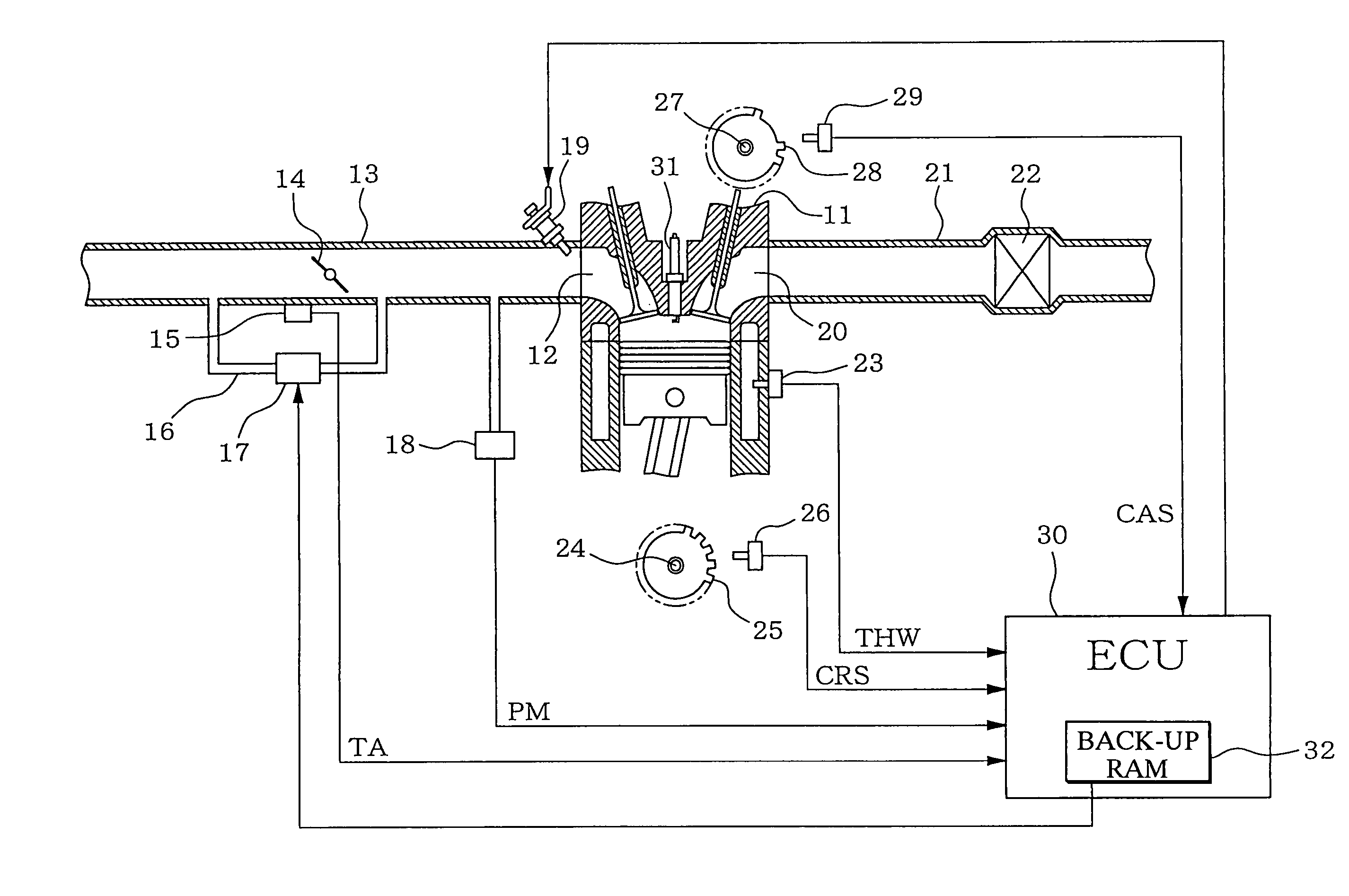
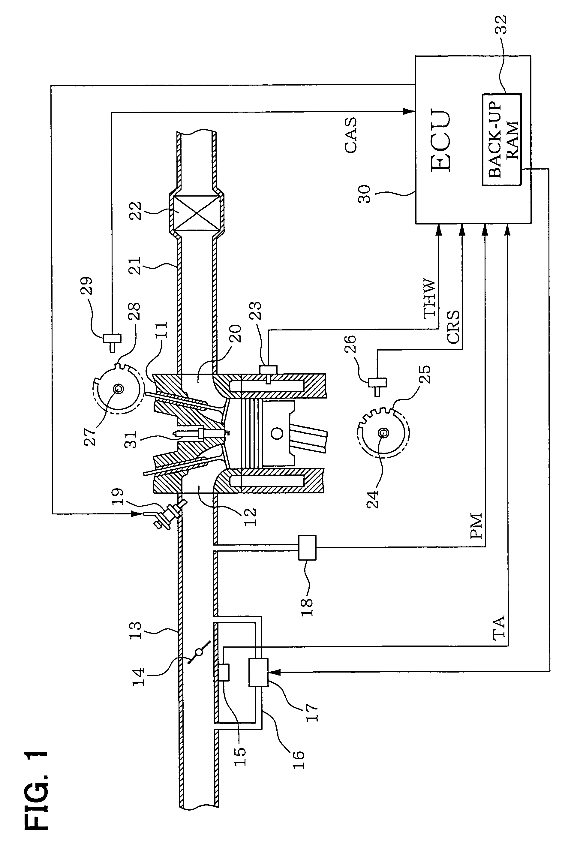
[0049]Referring first to FIG. 1, a throttle valve 14 is provided midway in an intake pipe 13 connected to intake ports 12 of an engine 11, and an opening degree (throttle opening degree) TA of the throttle valve 14 is detected by a throttle opening degree sensor 15. Provided in the intake pipe 13 is a bypass passage 16 to bypass the throttle valve 14, and provided midway the bypass passage 16 is an idling speed control valve (ISC valve) 17. Provided on the downstream side of the throttle valve 14 is an intake pipe pressure sensor 18 for detecting an intake pipe pressure PM, and mounted in the vicinity of the intake ports 12 of respective cylinders are fuel injection valves 19.

[0050]A catalyst 22 for purification of exhaust gases is installed midway in an exhaust pipe 21 connected to exhaust ports 20 of the engine 11. Provided on a cylinder block of the engine 11 is a cooling water temperature sensor 23 for detecting a cooling water temperature THW. A crank angle se...

second embodiment

(Second Embodiment)

[0107]A second embodiment of the present invention is also configured, as shown in FIG. 11, in the same manner as the first embodiment (FIG. 1).

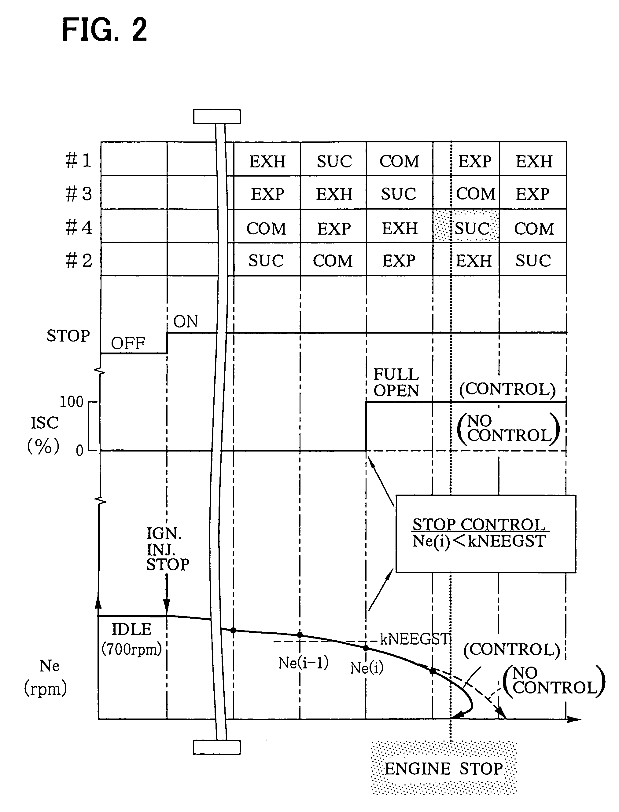
[0108]According to the second embodiment, an engine rotation stop position is estimated as indicated in a time chart in the course of engine stop shown in FIG. 14. An instantaneous engine rotational speed Ne at respective compression TDCs is used as a parameter representative of engine operation. The ECU 30 measures a period of time required for rotation of the crankshaft 24 over, for example, 30° CA on the basis of output intervals of crank pulse signals CRS to calculate the instantaneous rotational speed Ne.

[0109]Here, energy balance at an i-th compression TDC (TDC(i)) in FIG. 14 is considered. Pumping loss, friction loss in respective parts, and driving loss in respective auxiliary devices are taken into account as work to obstruct engine operations. Assuming kinetic energy of an engine at a point of time TDC(i−1) to be...

third embodiment

(Third Embodiment)

[0131]In the second embodiment, whether engine rotation is stopped is determined depending upon a predicted value of an instantaneous rotational speed at TDC being the first in the future, so that an engine rotation stop position is estimated just before engine rotation is stopped.

[0132]Hereupon, according to the third embodiment, the processing of estimating a further future instantaneous rotational speed is repeated by the use of a predicted value of a future instantaneous rotational speed and a parameter for obstructing motions, until it is determined that engine rotation is stopped, so that an engine rotation stop position can be estimated even not just before engine rotation is stopped.

[0133]A method of estimating an engine rotation stop position, according to the third embodiment is described below with reference to a time chart shown in FIG. 17. A parameter Cstop for obstructing engine operations, and a predicted value of an instantaneous rotational speed Ne...


PUM


Abstract

A control apparatus for an engine increases an intake air quantity just before engine stop to increase a compression pressure in a compression stroke. As the compression pressure is increased, a negative torque in the compression stroke increases and obstructs engine rotation, and brakes the engine rotation. Thus, a range of crank angle, in which torque is below engine friction, that is, in which engine rotation can be stopped, is reduced. As a result, variation in engine rotation stop position is reduced to be within a small range of crank angle. Information of engine rotation stop position is stored, and the stored information of engine rotation stop position is used at the start of an engine to accurately determine an initial injection cylinder and an initial ignition cylinder to start the engine.

Description

CROSS REFERENCE TO RELATED APPLICATION[0001]This application is based on and incorporates herein by reference Japanese Patent Applications No. 2003-21562 filed on Jan. 30, 2003, No. 2003-34579 filed on Feb. 13, 2003 and No. 2003-34580 filed on Feb. 13, 2003.FIELD OF THE INVENTION[0002]The present invention relates to an apparatus for controlling engine rotation stop, estimating a rotation stop position and estimating kinetic energy.BACKGROUND OF THE INVENTION[0003]Generally, ignition control and fuel injection control are performed in engine operation by determining cylinders on the basis of output signals from a crank angle sensor and a cam angle sensor and detecting a crank angle. However, a cylinder for initial ignition / injection is not known at the start of an engine until the engine is cranked by a starter and determination of a specified cylinder is completed, that is, a signal of a predetermined crank angle of the specified cylinder is detected.[0004]In order to solve such a ...

Claims


Application Information

Patent Timeline
IPC IPC(8): G06G7/70F02P7/077F02D41/04F02D41/06F02D41/10
CPCF02D41/042F02D41/065F02D41/102F02D41/0002F02D2041/0095F02N99/006F21V23/026F21V29/508F21V29/76F21V29/83H05B41/02
Inventor NISHIKAWA, SEIICHIROUMURAKAMI, YOSHIFUMI
Owner DENSO CORP
Why Eureka
Try Eureka