Sealing interface for microfluidic device

a technology of microfluidic devices and interfaces, which is applied in the field of microfluidic systems, can solve the problems of inability to perform multiple parallel separations, inability to rapidly operate, and inability to meet the needs of high-throughput (i.e., parallel) separation systems

Active Publication Date: 2006-04-18
AGILENT TECH INC
View PDF114 Cites 93 Cited by
  • Summary
  • Abstract
  • Description
  • Claims
  • Application Information

AI Technical Summary

Problems solved by technology

Nonetheless, the ability to perform multiple parallel separations has been limited for a variety of reasons.
One obstacle to the development of parallel high-pressure fluidic systems has been providing fluidic interconnects capable of rapid operation while reliably sealing against leakage of high-pressure fluids.
These fittings, however, are not well-suited for use in high-throughput (i.e., parallel) separation systems because: (1) they typically require individual assembly, which limits their ability to be rapidly operated; (2) they typically require circumferential access, thus limiting their ability to be arranged in close proximity to one another; and (3) they are difficult to automate due to the need to perform steps such as aligning mating components, rotating multiple screw fittings, and so on.
One limitation of the Holl et al. interconnect is that it requires elastomeric materials.
Elastomeric materials have limited utility in applications such as liquid chromatography, however, since they are generally incompatible with organic solvents typically used in chromatography and also may interact with samples in undesirable ways.
For example, organic solvents commonly used in liquid chromatography can degrade elastomeric materials, thus causing degradation products to enter an eluate stream and potentially interfere with sample analysis.
Additionally, molecules of a first sample may be adsorbed or otherwise temporarily bound to an elastomeric material during a first separation run, and such molecules may subsequently leach into an eluate stream containing a second sample during a second separation run, thus causing cross-contamination.
Moreover, elastomeric materials are subject to mechanical wear, thus conferring limited service life to components constructed with them.
Certain of these sealing methods are ill suited for multi-use chromatography systems.
O-rings are often ill-suited for repeated connection / disconnection cycles since they can come loose from their associated bosses or retention structures.
In another example, the use of adhesives or material joining techniques utilizing direct bonding or ultrasonic welding usually provide permanent connections that may be incompatible with device designs that require temporary connections to enable periodic access to fluidic ports, such as for loading samples.
If releasable (non-permanent) adhesives are used, the resulting interconnects typically pose chemical compatibility problems and may not seal against high operating pressures.
Notably, Swedberg lacks details regarding specific channel configurations or other structures adapted to permit reliable fluidic interfaces at high operating pressures.

Method used


Image

  • Sealing interface for microfluidic device
  • Sealing interface for microfluidic device
  • Sealing interface for microfluidic device

Examples


Embodiment Construction

Definitions

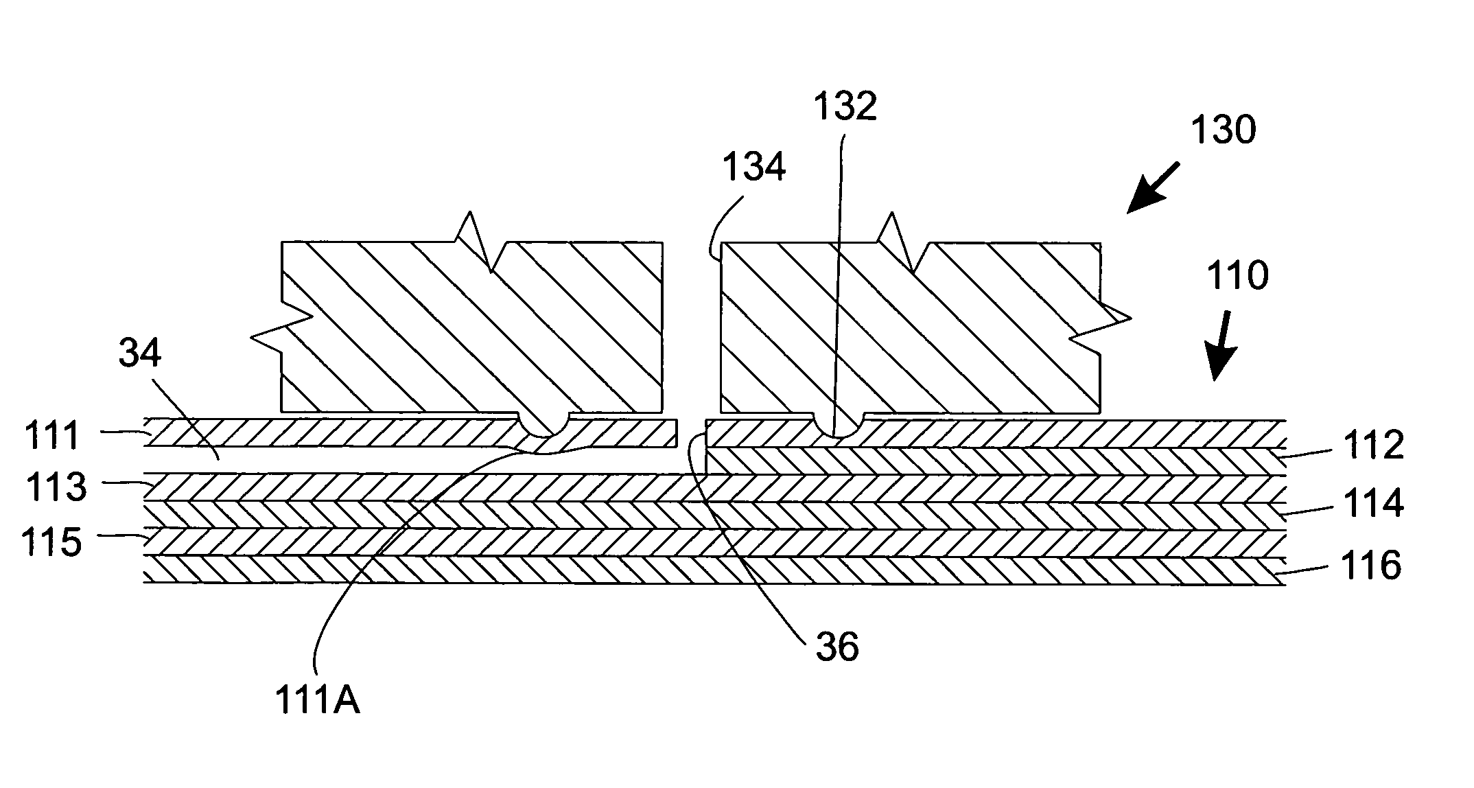
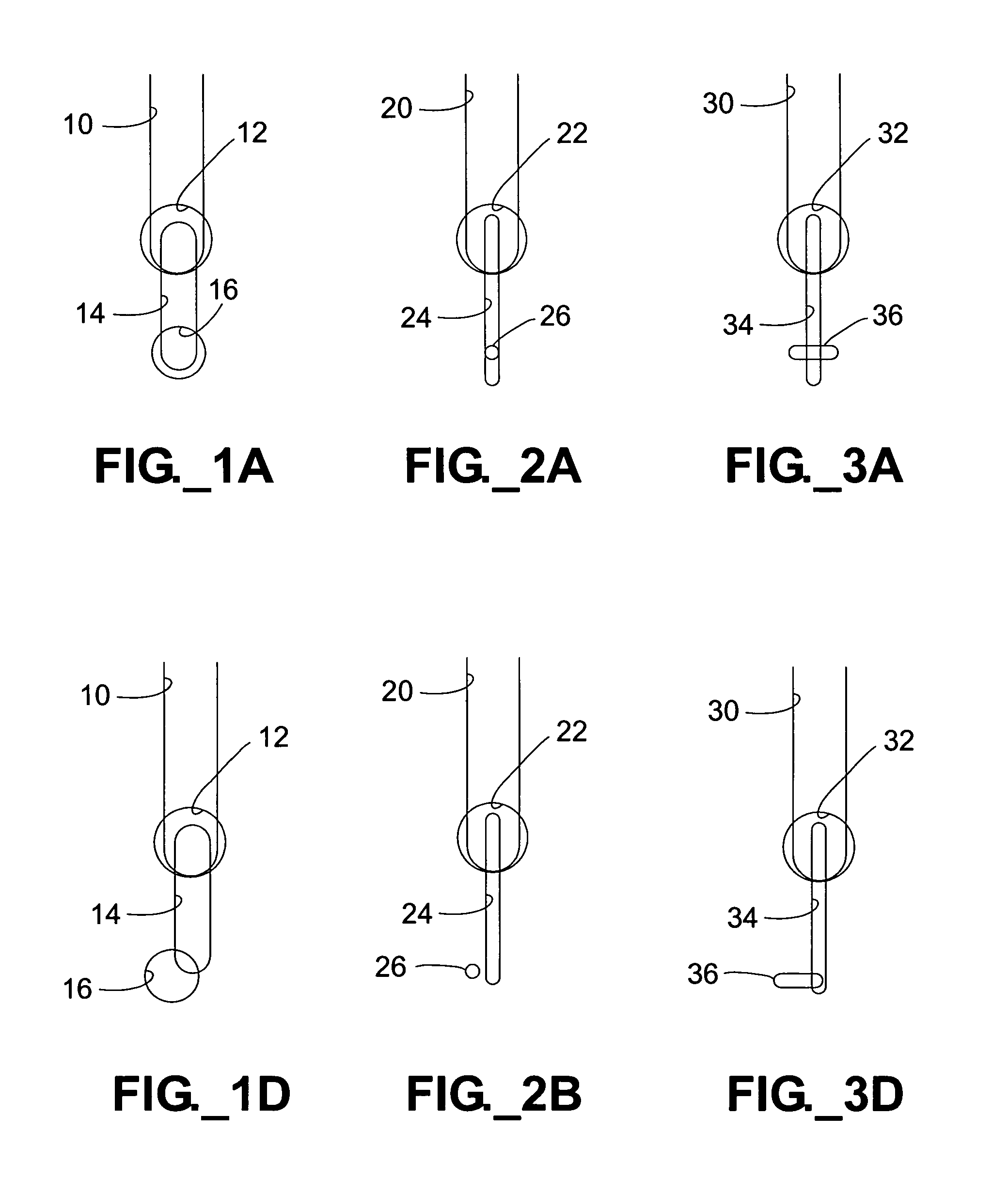
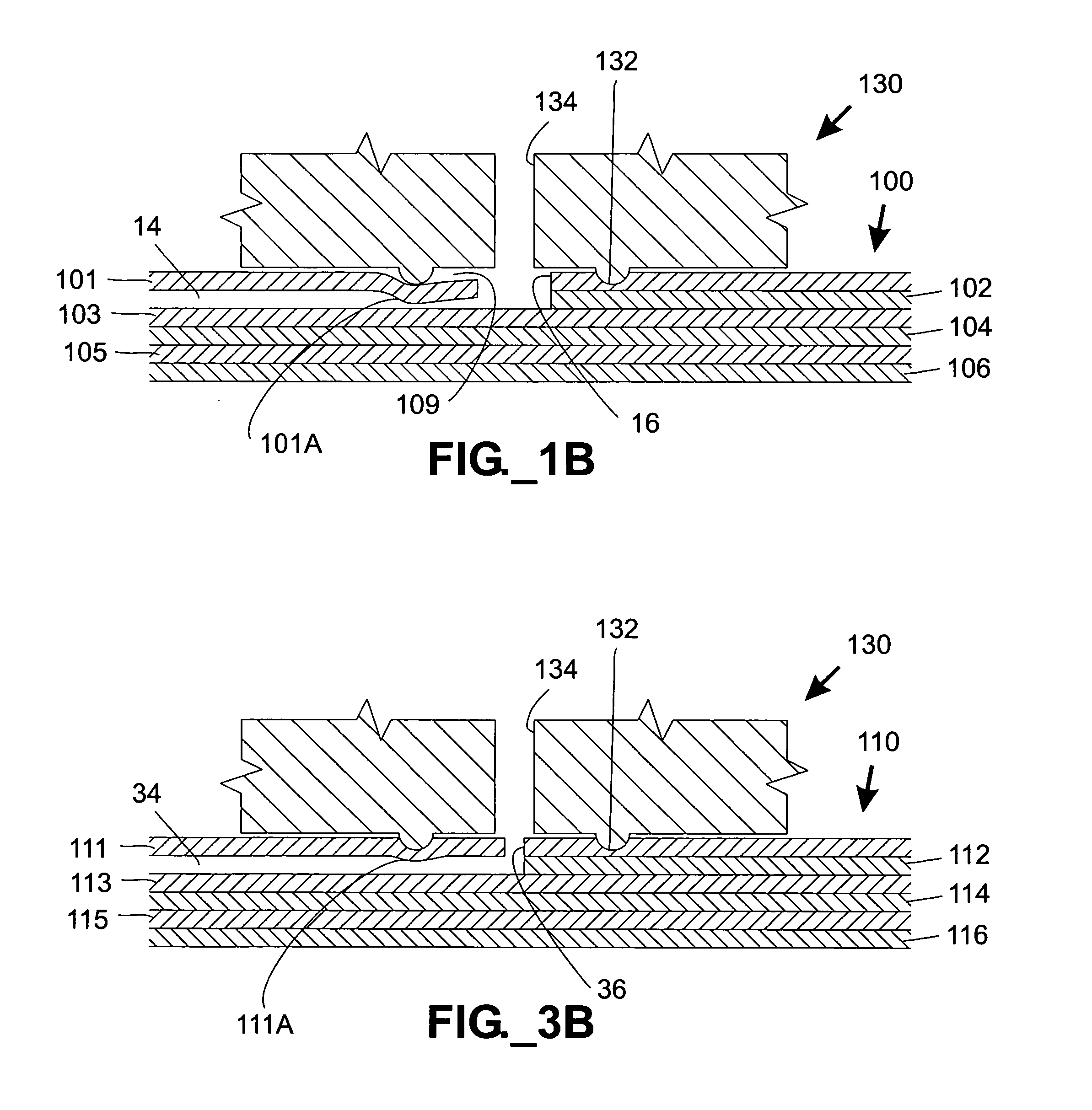
[0030]The term “collapse” as used herein refers to a substantially complete closure or blockage of a fluidic channel, such as may be caused by compressing the upper and lower boundaries of a channel together.

[0031]The terms “column” or “separation column” as used herein are used interchangeably and refer to a region of a fluidic device that contains stationary phase material and is adapted to perform a separation process.

[0032]The term “depth” as used herein with regard to a microfluidic channel structure refers to the distance between the outer surface of a microfluidic device and the parallel channel surface nearest to the outer surface. For example, if depth of a channel is measured relative to an upper surface of a microfluidic device, the depth is equal to the distance between the upper boundary of the channel and the upper (outer) surface of the device.

[0033]The term “elastomer” as used herein refers to a polymeric material that is crosslinked to form a network stru...


PUM

PropertyMeasurementUnit
contact pressureaaaaaaaaaa
pressureaaaaaaaaaa
pressureaaaaaaaaaa

Abstract

A threadless interface for a fluidic system includes a microfluidic device having an outer surface and an internal near-surface channel having a first width and disposed at a first depth relative to the outer surface, with the first width being less than about two times the first depth. A fluidic seal engages the outer surface and exerts an elevated contact pressure against at least a portion of the outer surface without substantially occluding the channel. A preferred seal includes a raised boss. A fault tolerant flow path design can accommodate misalignment between adjacent device layers without detrimentally affecting fluid flow capability. The interface may be used in a microfluidic system for performing parallel analyses such as high performance liquid chromatography.

Description

FIELD OF THE INVENTION[0001]The present invention relates to microfluidic systems, including microfluidic devices for handling and / or processing very small quantities of fluids and associated interfaces.BACKGROUND OF THE INVENTION[0002]There has been a growing interest in the application of microfluidic systems to a variety of technical areas, including such diverse fields as biochemical analysis, medical diagnostics, chemical synthesis, and environmental monitoring. Microfluidic systems provide certain advantages in acquiring chemical and biological information. For example, microfluidic systems permit complicated processes to be carried out using very small volumes of fluid, thus minimizing consumption of both samples and reagents. Chemical and biological reactions occur more rapidly when conducted in microfluidic volumes. Furthermore, microfluidic systems permit large numbers of complicated biochemical reactions and / or processes to be carried out in a small area (such as within a...

Claims


Application Information

Patent Timeline
Patent Type & Authority Patents(United States)
IPC IPC(8): G01N30/00B01L3/00G01N30/60
CPCB01L3/502715B01L3/565G01N30/6095G01N30/6026B01L3/50273B01L2200/027B01L2300/0816B01L2400/0487B01L2200/0689
Inventor KARP, CHRISTOPH D.PEZZUTO, MARCIHOBBS, STEVEN E.
Owner AGILENT TECH INC
Why Eureka
Try Eureka