Solid electrolytic capacitor and electric circuit

a solid electrolytic capacitor and electric circuit technology, applied in the direction of liquid electrolytic capacitors, fixed capacitors, fixed capacitor details, etc., can solve the problems of increasing the difficulty of reducing the impedance in the ultra high frequency range, high capacitance, and high tolerable power loss, so as to achieve low esr and low esl. , the effect of large capacitan

Inactive Publication Date: 2006-04-18
ROHM CO LTD
View PDF7 Cites 53 Cited by
  • Summary
  • Abstract
  • Description
  • Claims
  • Application Information

AI Technical Summary

Benefits of technology

[0010]The present invention is conceived under the circumstances described above. It is, therefore, an object of the present invention to provide a solid electrolytic capacitor which has large capacitance, low ESR and low ESL and which is capable of suppressing heat generation to cope with an increase of the current and enhancing the tolerable power loss. Another object of the present invention is to provide an electric circuit utilizing such a solid electrolytic capacitor.
[0013]Preferably, the cathode is provided with a cathode terminal electrically connected to the solid electrolytic layer, and the inductance of the bypass current path is higher than the equivalent series resistance of a route from the input anode terminal to the cathode terminal through the anode body.
[0014]Preferably, the cathode is provided with a cathode terminal electrically connected to the solid electrolytic layer, and the inductance of the bypass current path is lower than the equivalent series resistance of a route from the input anode terminal to the cathode terminal through the anode body.

Problems solved by technology

Further, in accordance with high current power supply, high capacitance and high tolerable power loss are also demanded strongly.
Since the ESL increases as the volume of the porous sintered body increases, to reduce the impedance in the ultra high frequency range becomes more difficult as the capacitance of the capacitor is increased.
Recently, however, an electronic device as the object of power supply often requires high direct current.
In this way, conventionally, it is difficult to improve the high frequency characteristics by reducing the ESL while increasing the tolerable power loss in accordance with the increase of the circuit current.

Method used


Image

  • Solid electrolytic capacitor and electric circuit
  • Solid electrolytic capacitor and electric circuit
  • Solid electrolytic capacitor and electric circuit

Examples


first embodiment

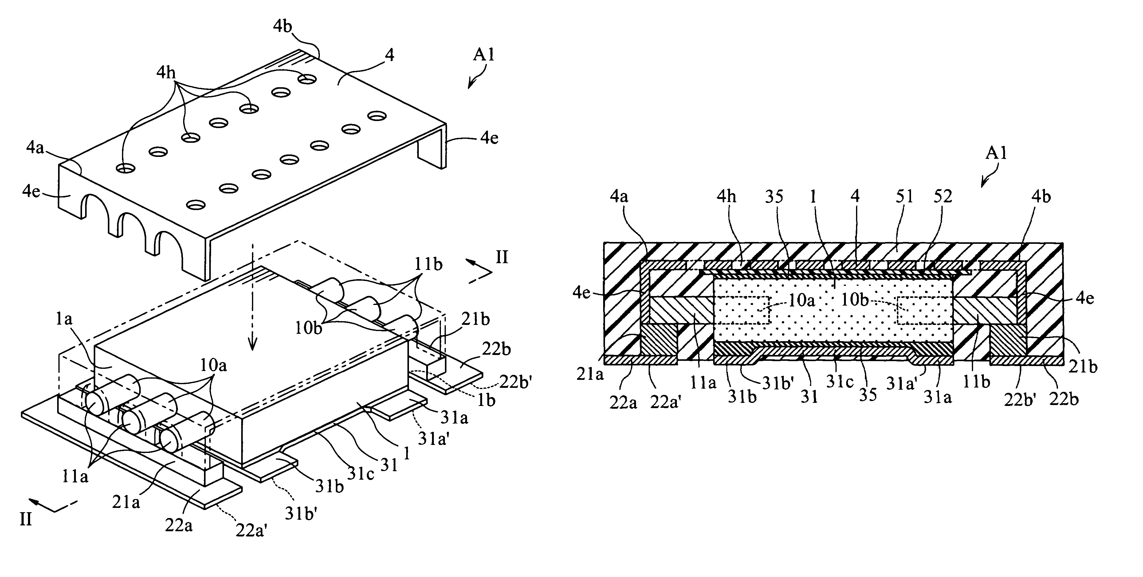
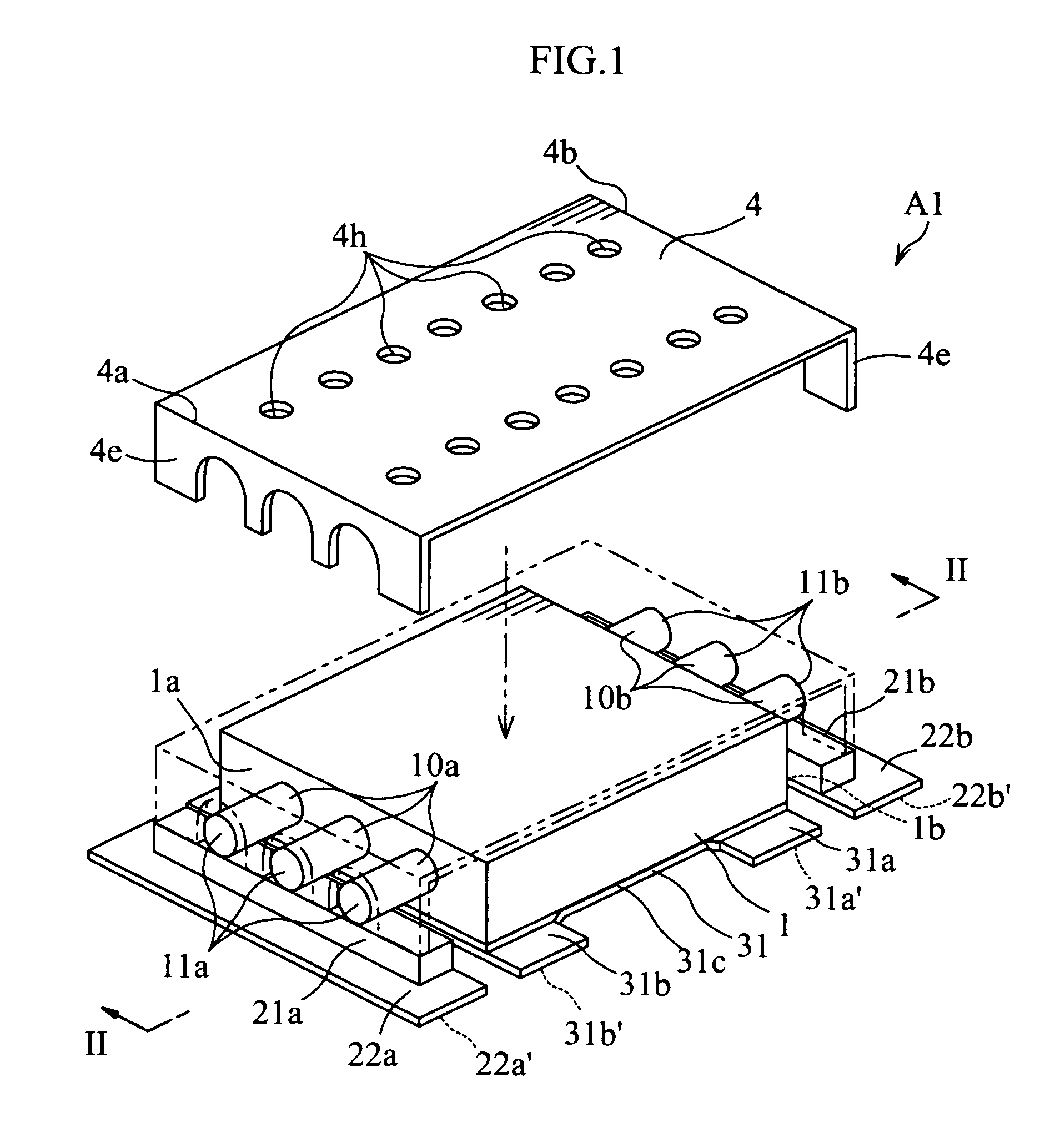
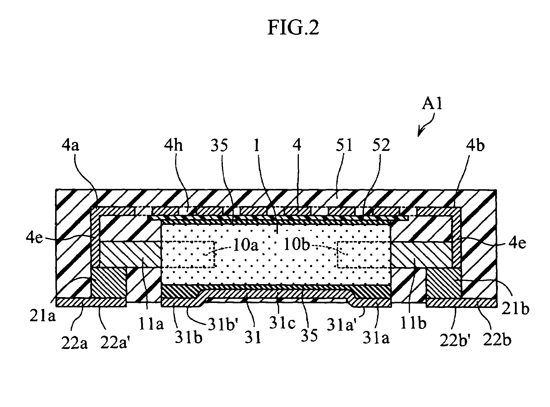
[0066]FIGS. 1 and 2 show a solid electrolytic capacitor according to the present invention. The illustrated solid electrolytic capacitor A1 includes a porous sintered body 1, six anode wires 10a and 10b, and a metal cover 4. As shown in FIG. 2, the solid electrolytic capacitor A1 further includes a sealing resin 51 covering the porous sintered body 1. In FIG. 1, the sealing resin 51 is omitted.

[0067]The porous sintered body 1 is made of niobium which is a kind of so-called “valve metal”. Specifically, the porous sintered body 1 is made by compacting niobium powder into the form of a rectangular plate and then sintering the compacted body. The porous sintered body 1 is an example of anode body of the present invention. On the porous sintered body 1 is formed a dielectric layer (not shown), on which a solid electrolytic layer (not shown) is formed. The solid electrolytic layer constitutes a cathode of the present invention. As the material of the porous sintered body 1, tantalum, for ...

second embodiment

[0087]FIGS. 7 and 8 show a solid electrolytic capacitor A2 according to the present invention. As will be understood from the figures, the capacitor A2 includes three porous sintered bodies 1 stacked together. Two adjacent ones of the porous sintered bodies 1 are bonded together by conductive resin 35 via a flat metal plate 32. The cathode terminals 32a, 32b of each metal plate 32 and external cathode terminals 31a, 31b are formed with holes in which a plurality of connection members 36 are provided to penetrate threrethrough. As a result, the metal plate 31 and the two metal plates 32 are electrically connected to the solid electrolytic layers formed on the porous sintered bodies 1 and also electrically connected to each other. Similarly, three conductive members 21a, 21b are formed with holes, and a plurality of connection members 24 are provided to penetrate therethrough to electrically connect these members to each other. The connection members 24 and 36 are made of a metal havi...

third embodiment

[0089]FIG. 9 shows a solid electrolytic capacitor A3 according to the present invention. The capacitor A3 includes two porous sintered bodies 1 arranged in parallel. Each of the porous sintered bodies 1 includes two anode wires for inputting and two anode wires for outputting, whereby including two input anode terminals 11a and two output anode terminals 11b. The anode terminals 11a and 11b are electrically connected to an external anode terminal 22a for inputting and an external anode terminal 22b for outputting, respectively. Both of the solid electrolytic layers (not shown) formed at the two porous sintered bodies 1 are electrically connected to a metal plate 31. The metal cover 4 has a size capable of housing the two porous sintered bodies.

[0090]With such a structure again, similarly to the structure shown in FIGS. 7 and 8, the capacitance of the capacitor can be increased. The input anode terminals 11a and the output anode terminals 11b are arranged close to the external anode ...


PUM


Abstract

A solid electrolytic capacitor includes a cathode including a solid electrolytic layer, an anode, and a dielectric layer provided between the cathode and the anode. The anode includes an anode body, an input anode terminal and an output anode terminal. A bypass current path for causing circuit current to detour around the anode body is formed between the input anode terminal and the output anode terminal.

Description

BACKGROUND OF THE INVENTION[0001]1. Field of the Invention[0002]The present invention relates to a solid electrolytic capacitor. The invention also relates to an electric circuit using a solid electrolytic capacitor.[0003]2. Description of the Related Art[0004]As an example of solid electrolytic capacitor, there exists a so-called three-terminal solid electrolytic capacitor. (See JP-A 2003-158042, for example.) In such a solid electrolytic capacitor, the circuit current flows from an input anode terminal through an anode body toward an output anode terminal for realizing low impedance in a wide frequency range.[0005]For example, JP-A 2003-163137 discloses a solid electrolytic capacitor which is excellent in terms of high capacitance, low ESL (equivalent series inductance) and low ESR (equivalent series resistance). The capacitor includes an anode body formed of a porous sintered body made of so-called “valve metal” such as tantalum or niobium.[0006]The solid electrolytic capacitor h...

Claims


Application Information

Patent Timeline
Patent Type & Authority Patents(United States)
IPC IPC(8): H01G9/04H01G4/228H01G2/00H01G9/28H01G9/00H01G9/012H01G9/048H01G9/052H01G9/14H01G9/15
CPCH01G9/012H01G9/15H01G9/14
Inventor KURIYAMA, CHOJIRO
Owner ROHM CO LTD
Why Eureka
Try Eureka