Piezo actuator drive circuit

a technology of actuator and drive circuit, which is applied in the direction of electrical control, device details, and piezoelectric/electrostrictive device details, etc., can solve the problems of difficult to obtain a constant amount of displacement, difficult to completely remove the error of constant energy supply quantity, and difficult to control the charging amount of piezo stacks. the effect of accurate control of the charging amoun

Active Publication Date: 2006-04-25
DENSO CORP
View PDF8 Cites 29 Cited by
  • Summary
  • Abstract
  • Description
  • Claims
  • Application Information

AI Technical Summary

Benefits of technology

[0014]In consideration of these circumstances, the present invention has an object to provide a piezo actuator drive circuit that can control piezo stacks with high precision regardless of the variation among the piezo stacks, etc.
[0015]According to the present invention, a piezo stack that can be driven by charging and discharging is charged in a charging amount for a predetermined charging period. The charging amount is calculated. The calculated amount and a target charging amount are compared. The charging amount during the next charging process is corrected according to the difference between the compared amounts. Thus, the charging amount in which the piezo stack is charged for the preset constant charging time and the target charging amount, which may depend on the variation among piezo stacks, are compared. The charging amount is corrected according to the difference between the compared amounts during the next charging process. Accordingly, the charging amount in which the piezo stack is charged can be controlled accurately without being influenced by the variation among piezo stacks, etc.

Problems solved by technology

Even if this capacitance decreases, the speed at which the charging current decreases on the whole is not very high either.
For this reason, it is difficult to completely remove the error of constant energy supply quantity due to the variation among piezo stacks 7.
Accordingly, it has been difficult to obtain a constant amount of displacement if the amounts of energy with which the piezo stacks are charged for the constant amount of displacement vary due to the variation among the piezo stacks.

Method used


Image

  • Piezo actuator drive circuit
  • Piezo actuator drive circuit
  • Piezo actuator drive circuit

Examples


first embodiment

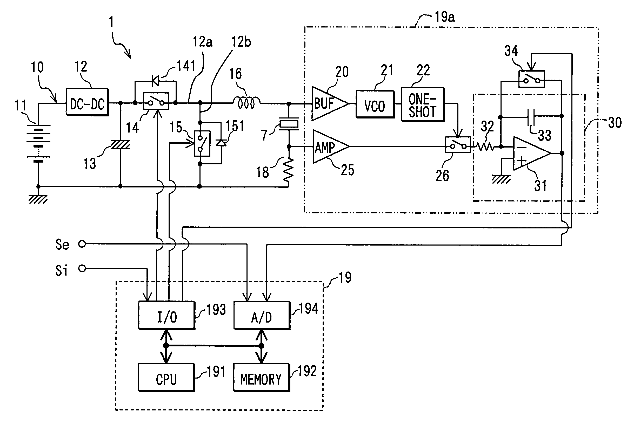
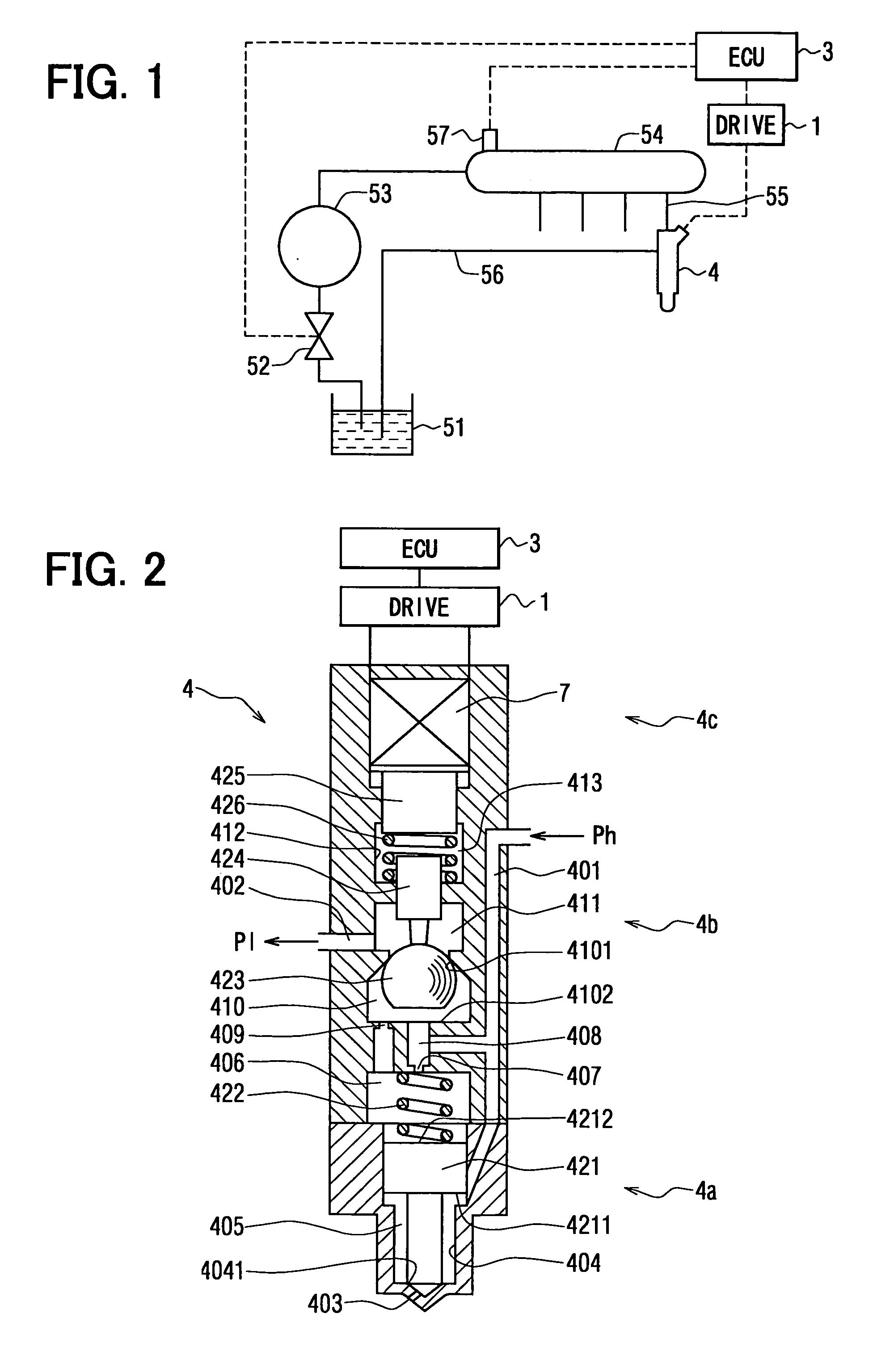
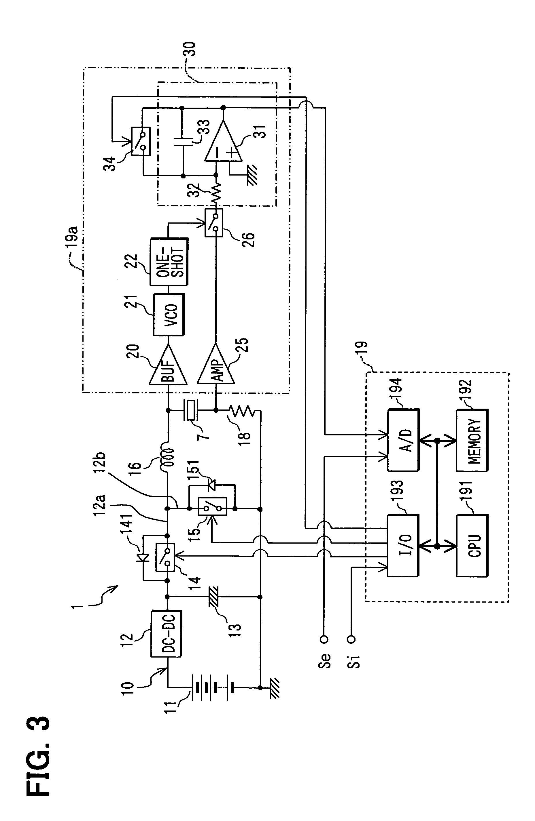
[0028]Referring to FIG. 1, a fuel injection system for a common-rail four-cylinder diesel engine, which may be a four-cylinder engine, is shown. The fuel injection system includes a piezo actuator drive circuit 1, which is a multiple switching circuit constructed as shown in FIG. 3.

[0029]The diesel engine has fuel injectors 4, only one of which is shown, and each of which is fitted to one of the engine cylinders. The injectors 4 are supplied with fuel from a common rail 54, each through a supply line 55. The injectors 4 can inject fuel into the combustion chambers of the respective cylinders with an injection pressure roughly equal to the common rail pressure, which is the fuel pressure in the common rail 54. The common rail 54 is supplied with fuel under pressure from a fuel tank 51 by a high pressure supply pump 53 and stores it under high pressure. A part of the fuel supplied to each injector 4 can be injected into the associated combustion chamber. The other part of the supplied...

second embodiment

[0096]The second embodiment shown in FIG. 6 is different from the first embodiment as follows.

[0097]A junction between the amplifier 25 and the third switching device 26 is connected with the A / D converter circuit 194 of the driving control circuit 19.

[0098]The charging current value, which is output from the current sensing resistor 18, is amplified by the amplifier circuit 25. The amplified current value is input through the third switching device 26 to the integrating circuit 30, as is the case with the first embodiment, and also input to the A / D converter circuit 194 of the driving control circuit 19. This makes it possible to determine the constant length Ton of the first ON period measured according to a preset current value, which is the peak value Ip of the charging current. During the subsequent predetermined charging period, the switching device 14 can be turned on and off repeatedly on the basis of the measured ON period Ton.

[0099]The method for comparing the amount of en...

third embodiment

[0107]In the second embodiment, the preset peak value Ip of the charging current is used for the measurement of the length Ton of the first ON period. On the basis of the ON period Ton, the first switching device 14 is turned on and off repeatedly. In the third embodiment of the present invention, as shown in FIG. 8, the first switching device 14 is turned on or off on the basis of a preset peak value Ip of the charging current during a charging period. The electric circuitry of a piezo actuator drive circuit 1 according to the third embodiment is also constructed as shown in FIG. 6.

[0108]The time chart of FIG. 9 shows:[0109](a) an injection signal Si as a driving signal;[0110](b) a charging time Tt;[0111](c) the ON-OFF characteristic of the first switching device 14;[0112](d) the charging voltage applied to the piezo stack 7;[0113](e) the charging current I flowing through the piezo stack 7;[0114](f) the output characteristic of the VCO circuit 21;[0115](g) pulses output from the o...


PUM


Abstract

A piezo actuator drive circuit comprises a charging path for charging a piezo stack that can be driven by being charged and discharged, an arithmetic circuit for calculating the charging amount for the piezo stack, and a driving control circuit for comparing the calculated charging amount and a target charging amount and correcting the charging amount during the next charging process according to the difference between the compared charging amounts. A charging current flowing through the piezo stack and a charging voltage applied to it may be measured during a charging process. It is preferable that the calculated charging amount be the amount of energy that is the result of the time quadrature of the product of the measured current and voltage.

Description

CROSS REFERENCE TO RELATED APPLICATION[0001]This application is based on and incorporates herein by reference Japanese Patent Applications No. 2003-51790 filed on Feb. 27, 2003 and No. 2003-410907 filed Dec. 9, 2003.FIELD OF THE INVENTION[0002]The present invention relates to a piezo actuator drive circuit.BACKGROUND OF THE INVENTION[0003]A piezo actuator utilizes the piezoelectric effect of PZT or another piezoelectric material and has a piezo stack, which is a capacitive element. When the piezo stack is electrically charged or discharged, it expands or contracts, linearly moving a piston or the like. For example, in fuel injection systems for internal combustion engines, piezo actuators switch ON-OFF valves of fuel injectors.[0004]A piezo actuator has a temperature characteristic, in which the capacitance of its piezo stack changes with temperature. The amount of displacement of the piezo actuator based on the expansion, contraction or displacement of the piezo stack also changes ...

Claims


Application Information

Patent Timeline
Patent Type & Authority Patents(United States)
IPC IPC(8): H01L41/08F02M51/00F02D41/20F02M51/06H01L41/04H01L41/083H02N2/00H02N2/06
CPCH01L41/042F02D41/2096H10N30/802
Inventor FUKAGAWA, YASUHIROSAKAKIBARA, YASUYUKITAKEMOTO, EIJI
Owner DENSO CORP
Why Eureka
Try Eureka