Antenna mounting printed-circuit board

Inactive Publication Date: 2006-04-25
SONY CORP
View PDF7 Cites 13 Cited by
  • Summary
  • Abstract
  • Description
  • Claims
  • Application Information

AI Technical Summary

Benefits of technology

[0021]According to the antenna mounting printed-circuit board of the invention as stated above, since the conductor pattern of the antenna element is made to have the three-dimensional structure, even in the case where the antenna element is constructed by using a substrate having a low dielec

Problems solved by technology

However, in the antenna element of such a type that it is disposed at the outside and is used, there are problems that miniaturization of the equipment is obstructed, high mechanical strength is required, and the number of parts is increased.
However, in this kind of antenna element, there are defects that the high dielectric constant material itself is expensive, and the processing thereof is troublesome, and t

Method used


Image

  • Antenna mounting printed-circuit board
  • Antenna mounting printed-circuit board
  • Antenna mounting printed-circuit board

Examples


Embodiment Construction

[0041]Hereinafter, a specific embodiment to which the invention is applied will be described in detail with reference to the drawings.

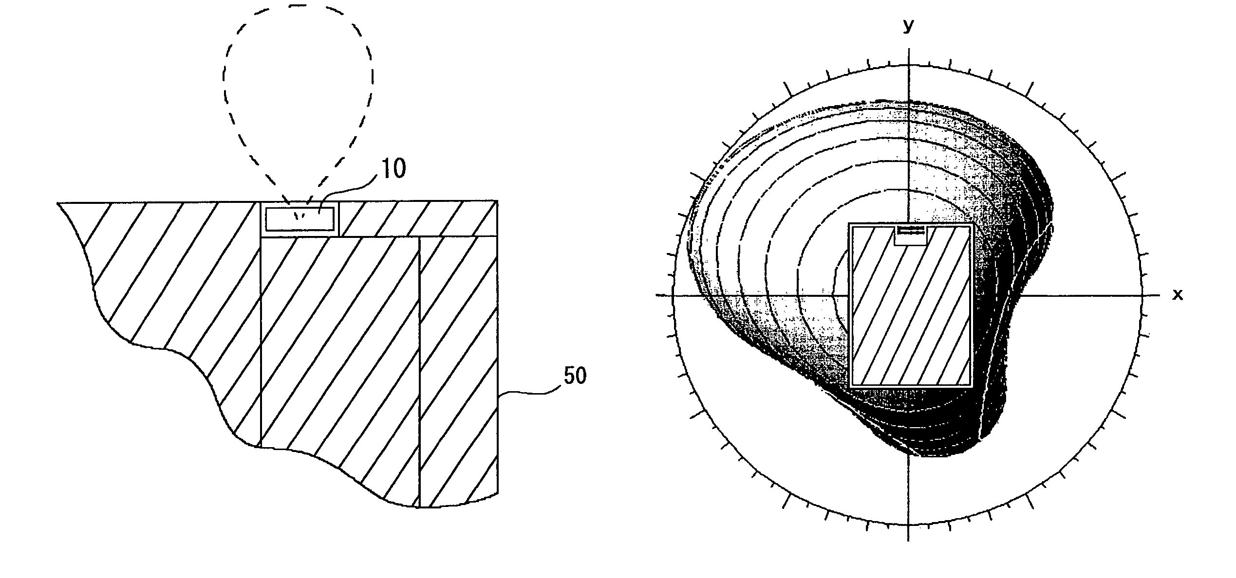
[0042]The embodiment is a printed-circuit board which is incorporated in the inside of an equipment having at least a communication function, for example, a mobile communication unit such as a cellular phone, or a wireless LAN (Local Area Network) according to the so-called IEEE (Institute of Electronic and Electronics Engineers) 802.11 standard, and mounts thereon a chip-like antenna element called a printed antenna in which an antenna conductor is patterned and formed on a specified resin substrate as a base member. This printed-circuit board mounts thereon one or plural other modules for realizing functions of an equipment body, together with the printed antenna, and mounts thereon the printed antenna which is not easily influenced by a ground existing in the surroundings, rather, actively uses the ground existing in the surroundings to perform mat...


PUM


Abstract

A chip-like printed antenna in which an open end is formed by at least two antenna conductors separated from each other is mounted on a printed-circuit board. A ground required by one or plural other modules is disposed and mounted on the printed-circuit board so as to surround a remaining area of a surrounding area of the printed antenna except a partial area as indicated by oblique line parts. By this, in the printed-circuit board , a radiation electric field does not come to have a dipole mode, but is formed into a balloon shape and is radiated in one direction as indicated by a broken line.

Description

BACKGROUND[0001]1. Technical Field[0002]The present invention relates to an antenna mounting printed-circuit board which is incorporated in an equipment having at least a communication function and mounts thereon various modules for realizing various functions.[0003]2. Technical Art[0004]In recent years, for example, like a mobile communication unit such as a cellular phone, or a wireless LAN (Local Area Network) based on the so-called IEEE (Institute of Electronic and Electronics Engineers) 802.11 standard, various wireless communication techniques have been remarkably developed, and in accordance with this, various techniques concerning an antenna element as an inevitably provided member to perform wireless communication have also been developed.[0005]As an antenna element, for example, one in which a radiation electrode, a surface electrode or the like is formed on a cylindrical dielectric is known. This kind of antenna element is generally installed at the outside of an equipmen...

Claims


Application Information

Patent Timeline
IPC IPC(8): H01Q1/38H01Q23/00H01Q1/22H01Q1/24H01Q9/04H05K1/16
CPCH01Q1/22H01Q1/2266H01Q1/2275H01Q1/38H01Q9/0421H01Q1/243H05K1/16H01Q1/24H05K1/02
Inventor ASAKURA, KENJIMURANAKA, HIDENOBUYASUDA, SHUICHIRO
Owner SONY CORP
Why Eureka
Try Eureka