Structure to achieve sensitivity and linear density in tunneling GMR heads using orthogonal magnetic alignments

a technology of orthogonal magnetic alignment and structure, applied in the field of magnetic transducers, can solve the problems of reducing the resistance and magnetoresistance of the stack, restricting the spacing of shields to shields, and the spin valves are not well suited to high linear density applications, so as to achieve the effect of improving sensitivity and linear density of the sensor structure and more sensitivity

Active Publication Date: 2006-04-25
SEAGATE TECH LLC
View PDF20 Cites 242 Cited by
  • Summary
  • Abstract
  • Description
  • Claims
  • Application Information

AI Technical Summary

Benefits of technology

[0010]Against this backdrop the present invention has been developed. The present invention provides a tunneling magneto-resistive or CPP spin valve read sensor structure that improves sensitivity and linear density of the sensor structure. The sensor includes first and second electrodes and a stack positioned between the electrodes. The stack includes first and second free layers with magnetization orientations, which in the absence of any external forces are aligned anti-parallel relative to each other by the magnetostatic interactions between the layers. The magnetization directions of the free layers are then brought into perpendicular alignment by some biasing technique. Examples of suitable biasing techniques are fields from external biasing magnets, or by exchange bias coupling of the free layers to antiferromagnetic layers, or by induced uniaxial anisotropy in the free layers, or by shape anisotropy, or by a combination of any of these mechanisms. A tunneling barrier (insulating or semiconducting layer), in the case of a tunneling magneto-resistive sensor, or a nonmagnetic metallic spacer, in the case of a CPP GMR sensor, is positioned between the first and second free layers. A sense current is passed between the first and second free layers of the stack. As the reader structure is passed over magnetically stored information in a medium disc, the magnetization of both free layers respond to the field emanating from the medium by rotating in opposite directions. The resistance of the read sensor then changes as it depends on the relative orientation of magnetization of the first and second free layers. This results in more sensitivity than the standard designs because both free layers respond and contribute to the output signal.

Problems solved by technology

The current can shunt through these pinholes and reduce the resistance and magnetoresistance of the stack.
Spin valves are not well suited to high linear density applications because they require half-gaps, which severely restricts how thin the shield-to-shield spacing can be.
However, the antiferromagnetic pinning layer of a tunnel junction occupies a large proportion of the total stack thickness and provides a further limit to the shield-to-shield spacing for current spin valve and TMR designs.
As the width of the sensor decreases, standard permanent magnet abutted junction designs have difficulty in stabilizing the free layer and maintaining an adequate output signal.
The larger the permanent magnet bias field the more stable the free layer response, but at the cost of increased free layer stiffness and lower output signal.
This is because a strong magnet field does not decay rapidly enough for narrow sensors, so the whole free layer is essentially pinned, resulting in very low amplitude.
On the other hand, a weak permanent magnet bias field is not strong enough to stabilize the free layer edges resulting in head instabilities.
Furthermore, shielding of stray magnetic fields originating from adjacent tracks also becomes an issue.
For these reasons, the viability of current spin valve and TMR abutted junction head designs is very questionable as areal density targets exceed 100 Gb / in2.

Method used


Image

  • Structure to achieve sensitivity and linear density in tunneling GMR heads using orthogonal magnetic alignments
  • Structure to achieve sensitivity and linear density in tunneling GMR heads using orthogonal magnetic alignments
  • Structure to achieve sensitivity and linear density in tunneling GMR heads using orthogonal magnetic alignments

Examples


embodiment 700

[0045]Another tri-layer CPP head embodiment 700, shown in FIG. 8, utilizes an in-stack bias scheme to make the two sensing layer biased orthogonal. Head 700 comprises a basic Trilayer CPP stack of free layers 730, 732 and an oxide spacer 734. Soft magnetic layers 770,772 are stabilized by AFM layers 760, 762, which provide unidirectional exchange fields at the FM / AFM interfaces. The FM / AFM layer pair is referred to as a soft-bias layer. This soft bias layer should be placed both on top of and underneath free layers 730, 732 with nonmagnetic spacer layers 780, 782. The magnetic flux from the soft-bias layer should be smaller than the magnetic flux of the free layer, resulting in a complete flux balanced structure that provides maximum magnetic stability performance. The structure of FIG. 8 may also offer several process advantages since there is no need to have lateral electrical insulation as in other embodiments. Seed layers and cap layers may also be needed to protect the stack.

[0...

embodiment 800

[0049]Another alternate stack embodiment 800 takes advantage of the ballistic magnetoresistance (BMR) in magnetic nanoconstrictions. It has been shown that BMR values of over 3000% can be achieved at room temperature in Ni nanocontacts at switching fields of only a few hundred oersteds. These values are two orders of magnitude larger than the magnetoresistance currently obtainable in standard CPP GMR and TMR designs. FIG. 10 shows a schematic of a stack 800 utilizing the ballistic MR effect. The stack consists of two free layers 832 and 842 separated by an insulating layer 834 with a nanobridge 836 in the insulating layer connecting the two free layers 832 and 842. The nanobridge 836 may be as small as 10 nm. Stack 620 includes a cap layer 830 contacting top shield 822, a first free layer 832, an insulating layer 834, a nanobridge in the insulating layer 834, a second free layer 842, a seed layer 820, and an electrode contacting bottom shield 824.

embodiment 900

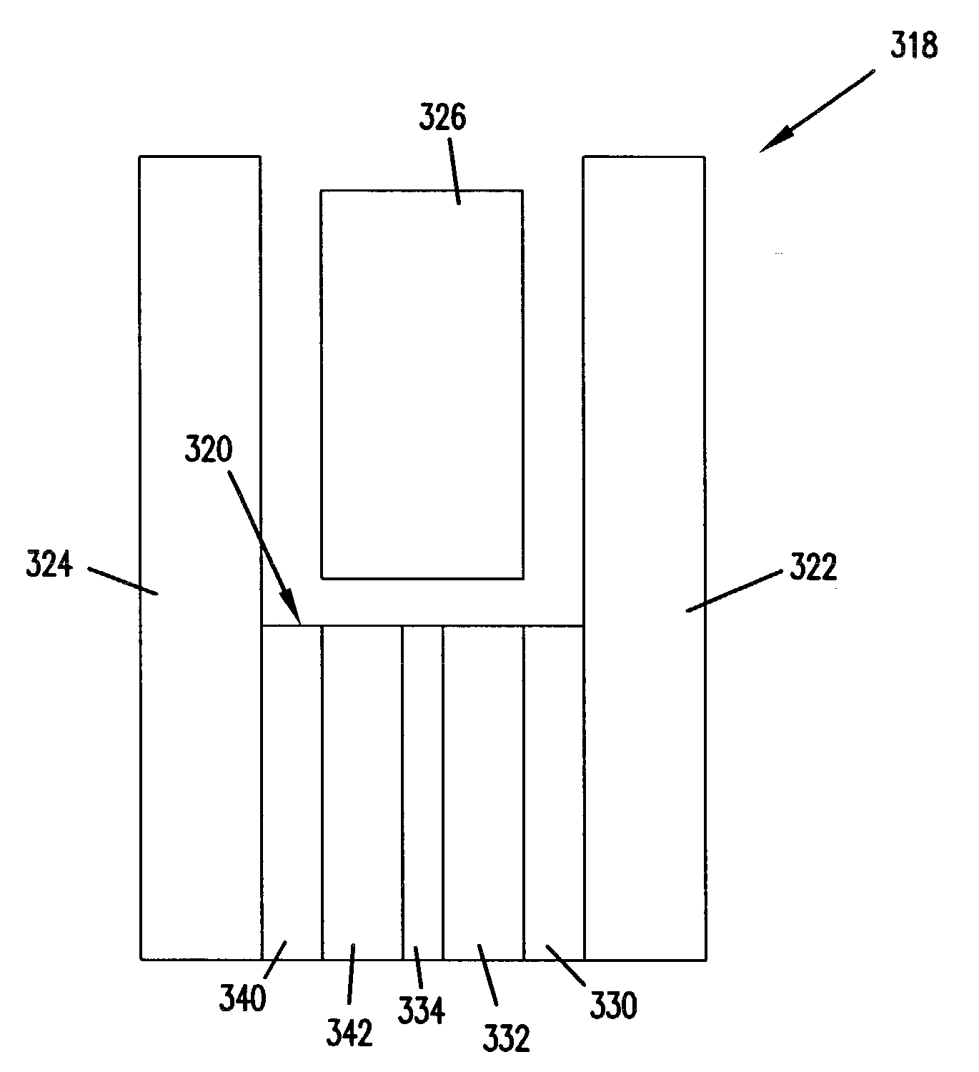
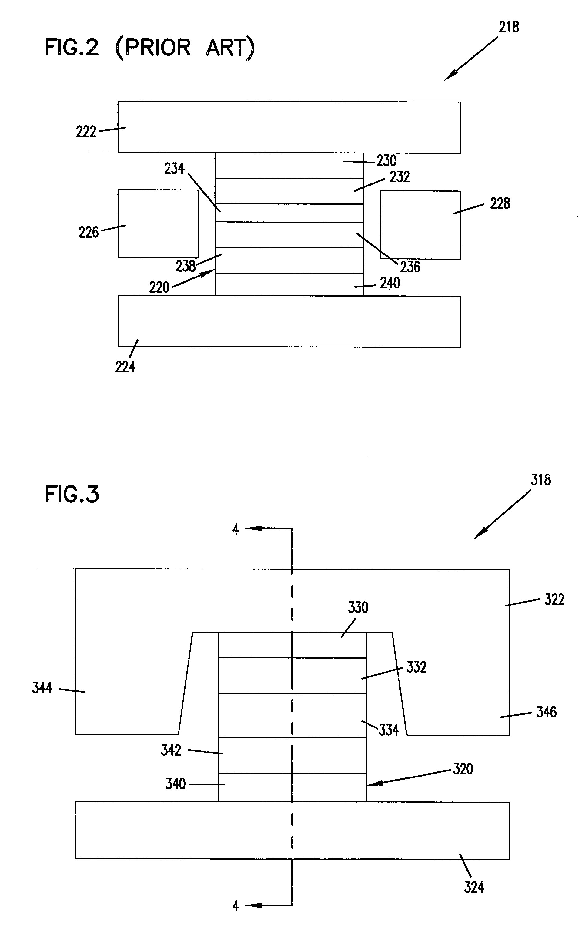
[0050]A further alternate stack embodiment 900, shown in FIG. 11, consists of multilayer free layers. In this case the barrier consists of an insulating, semiconducting, or non-magnetic metal spacer layer and each free layer consists of a series of ferromagnetic layers separated by non-magnetic spacer layers. This configuration leads to very strong ferromagnetic couplings between the ferromagnetic layers as a well as enhanced GMR / TMR effect. FIG. 11 shows a schematic of a stack 900 utilizing multilayer free layers. Stack 900 includes a cap layer 930 contacting a top shield 922, a first free layer 933, a semi-conducting layer or a non-magnetic metal layer 934, a second free layer 942, a seed layer 920, and an electrode-contacting bottom shield 924. The first and second free layers 933, 942 are further sub-divided into n repeat units 950 of ferromagnetic / non-magnetic spacer layers 952, 954. The non-magnetic spacer layer can be chosen to be any of the following: Cu, Ag, CuAg, CuAu, Ru,...


PUM

PropertyMeasurementUnit
thicknessaaaaaaaaaa
magnetoresistiveaaaaaaaaaa
magnetizationaaaaaaaaaa

Abstract

The present invention provides a tunneling magneto-resistive read sensor structure that improves sensitivity and linear density of the sensor structure. The sensor includes first and second electrodes and a stack positioned between the electrodes. The stack includes first and second free layers with magnetization orientations that are biased relative to each other. A tunneling barrier (insulating layer) or non-magnetic metal spacer is positioned between the first and second free layers. A sense current is passed between the first and second free layers of the stack. The amount of current passing through the first and second free layer changes based upon the orientation of the first and second free layers relative to each other.

Description

RELATED APPLICATIONS[0001]This application claims priority of U.S. provisional application Ser. No. 60 / 334,227, entitled “Structure To Achieve Sensitivity And Linear Density In Tunneling GMR Heads Using Orthogonal Magnetic Alignments” and filed Nov. 29, 2001.FIELD OF THE INVENTION[0002]This application relates generally to magnetic transducers for reading information bits from a magnetic medium, and more particularly to an improved structure for a tunneling magneto-resistive (TMR) or current-perpendicular-to-plane (CPP) giant magnetoresistance (GMR) read head or other type of CPP ballistic MR read head.BACKGROUND OF THE INVENTION[0003]A magneto-resistive (MR) element exhibits a change in electrical resistance as a function of external magnetic field. Such property allows MR elements to be used as magnetic field sensors, read heads in magnetic storage systems, and magnetic random-access-memories. In storage systems, the read head reads encoded information from a magnetic storage medi...

Claims


Application Information

Patent Timeline
Patent Type & Authority Patents(United States)
IPC IPC(8): G11B5/127
CPCB82Y10/00B82Y25/00G11B5/3909G11B5/3912H01F10/3218H01F10/3254G11B5/3932G11B2005/3996H01F10/1936
Inventor MAO, SININGLINVILLE, ERIC SHANEGAO, ZHENGKARR, BRIAN WILLIAMNOWAK, JANUSZ JOZEFHEINONEN, OLLE GUNNAR
Owner SEAGATE TECH LLC
Why Eureka
Try Eureka