Camera for directly generating a gradient image

a technology of gradient image and camera, applied in the field of sensing energy fields, can solve the problems of noise, motion blur, noise, and motion blur of both conventional analog and digital cameras, and achieve the effects of reducing quantization noise, reducing common-mode noise, and reducing nois

Inactive Publication Date: 2006-05-02
MITSUBISHI ELECTRIC RES LAB INC
View PDF3 Cites 63 Cited by
  • Summary
  • Abstract
  • Description
  • Claims
  • Application Information

AI Technical Summary

Benefits of technology

[0037]The invention measures the local gradients in the energy field directly in a single exposure. Therefore, common-mode noise is reduced. The invention can generate a detailed, high-contrast HDR output images that is not subject to pixel intensity sat

Problems solved by technology

However, the pixel values can also include the results of uncorrelated noise, e.g., noise due to heat, quantization errors, discrete electromagnetic flux, and imperfections in the sensors, circuits and process.
In many poorly lit scenes, it is difficult to avoid over-exposure, under-exposure, noise, and motion blur due to camera limitations.
Both conventional analog and digital cameras have exposure, lens and sensor limitations.
These limitations result in zoom-dependent chromatic aberration, color metamerism, color balance errors from mixed illumination, coupled zoom and focus adjustments, glare or ‘blooming’ of excessively brilliant objects, and lens flare caustics.
As a result, those systems only display selected features, and cannot reconstruct a complete output image from the original 2D intensity field.
The number of image generation methods that are known is too large to detail here.
However, those output images have a reduced linear resolution at higher intensities.
However, as stated above, the display intensity Id also includes noise due to discrete

Method used


Image

  • Camera for directly generating a gradient image
  • Camera for directly generating a gradient image
  • Camera for directly generating a gradient image

Examples


Embodiment Construction

System Overview

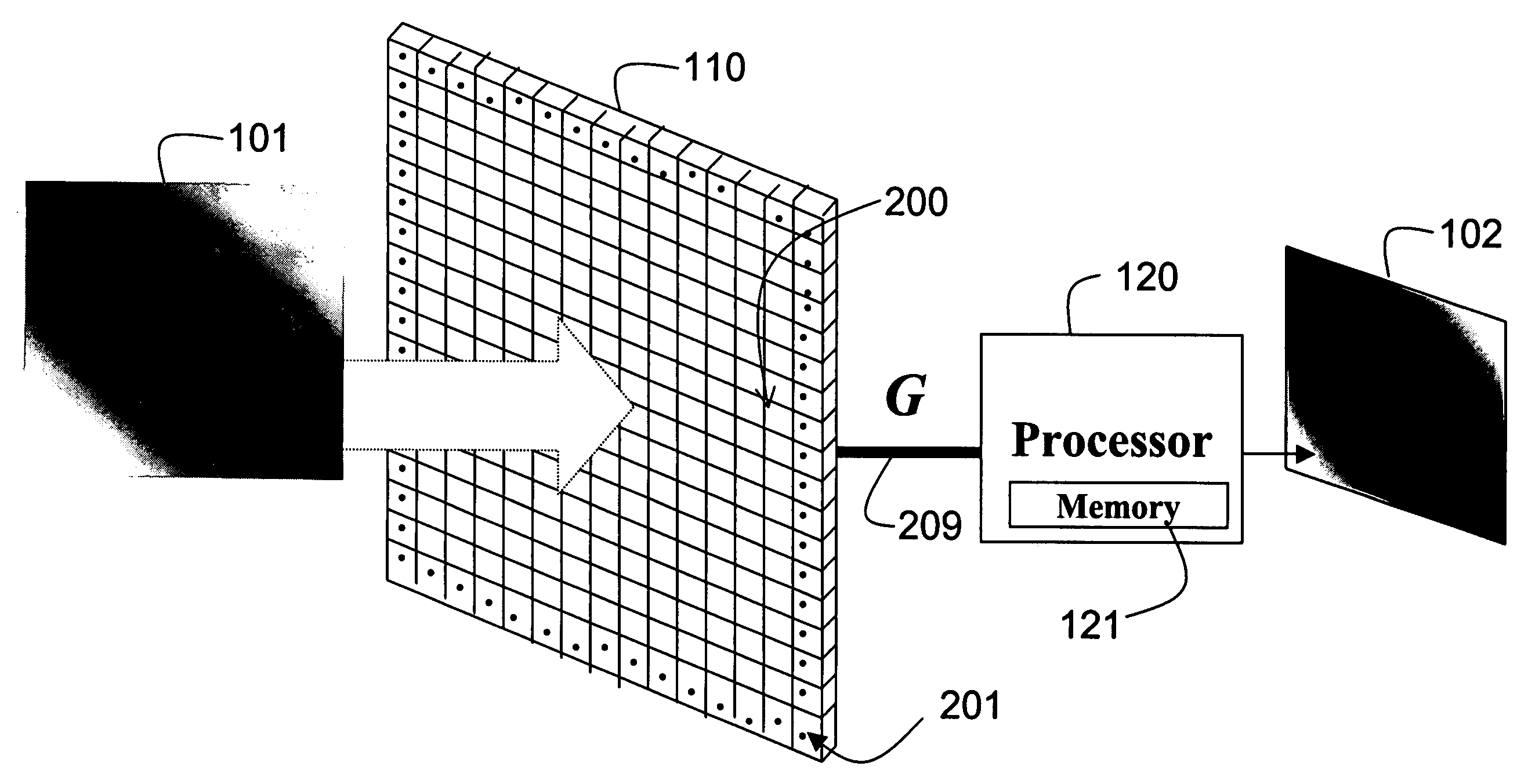
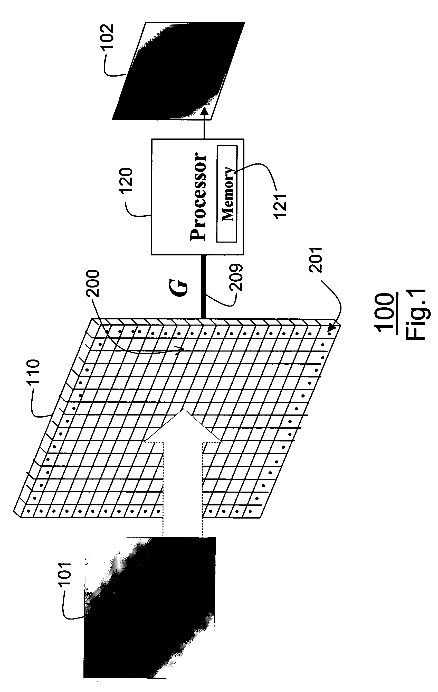
[0045]FIG. 1 shows a system 100, according to our invention. The system senses an energy field 101 and generates a digital output image 102 representing the sensed energy field, e.g., electromagnetic radiation, such as visible light.

[0046]Our system includes a set 110 of sensing elements 200. The set of sensing elements are spatially arranged in the energy field 101. For example, the elements 200 can be arranged at an image plane as an N×M array of elements as shown. Alternatively, the sensing elements can be arranged as an annular ring or cylinder 600, as shown in FIG. 6, to enable three-dimensional scanning of an energy field as used in medical and high energy physics applications. Other arrangements, such as 3D arrays, are also possible. In the preferred embodiment, the sensor elements 200 also include a set of boundary elements 201 at a periphery of the N×M array, as indicated by dots.

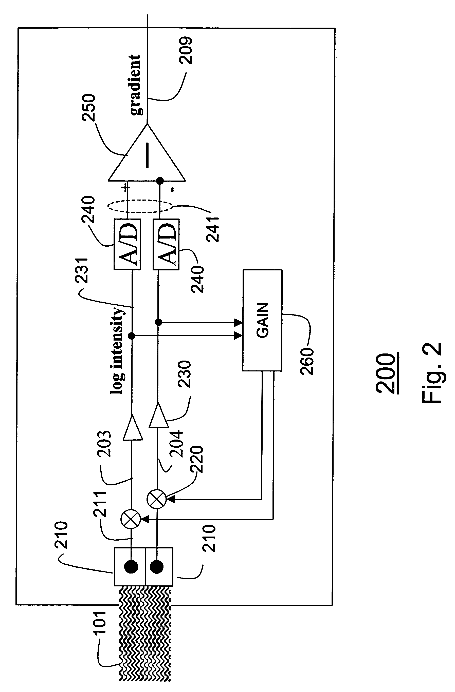
[0047]Gradient Sensing Elements

[0048]Each of our sensing elements 200 measures a...


PUM


Abstract

A camera includes a set of sensing elements. Each sensing element is arranged at an image plane in an energy field to measure a magnitude and sign of a local gradient of the energy field. Each sensing element includes at least two energy intensity sensors. Each energy sensor measures a local intensity of the energy field. Logarithms of the intensities are subtracted from each other to obtain the magnitude and sign of the gradients. A Poisson equation is solved using the gradients to obtain an output image of the energy field.

Description

FIELD OF THE INVENTION[0001]The invention relates generally to sensing energy fields, and more particularly to generating images with cameras.BACKGROUND OF THE INVENTION[0002]Cameras[0003]There are two well-known techniques for generating digital images. In the first technique, an analog film is exposed to an energy field, for example, visible light. The film is developed and digitized using a scanner. The resulting image includes pixel values that reflect the intensity distribution of the energy field. The image can also show the frequency distribution, or ‘color’ of the energy field.[0004]In the second technique, an array of digital sensors is arranged on an image plane in an energy field. The sensors measure the intensity of the energy directly. The sensors can also be made frequency selective by using filters. As an advantage, the second technique produces results immediately and does not consume any film. For these and other reasons, digital cameras are rapidly replacing analog...

Claims


Application Information

Patent Timeline
IPC IPC(8): H01L27/00G01J1/42H04N5/355H04N5/357H04N5/372
CPCH04N5/2355H04N5/355H04N5/335H04N5/2621H04N23/741H04N25/57H04N25/00
Inventor TUMBLIN, JACKAGRAWAL, AMITRASKAR, RAMESH
Owner MITSUBISHI ELECTRIC RES LAB INC
Why Eureka
Try Eureka