Horizontal current bipolar transistor and fabrication method

a bipolar transistor and horizontal current technology, applied in the field of bipolar transistor structures, can solve the problems of low efficiency inferior high-frequency characteristics of lateral pnp transistors compared to state-of-art silicon substrate devices, and poor electrical characteristics of cmos-based technology, so as to reduce the size of integrated circuit dies, reduce the area of chip surface, and improve the effect of lateral pnp transistors

Inactive Publication Date: 2006-05-02
RGT UNIV OF CALIFORNIA
View PDF6 Cites 25 Cited by
  • Summary
  • Abstract
  • Description
  • Claims
  • Application Information

AI Technical Summary

Benefits of technology

[0010]The present invention comprises a new type of bipolar transistor for use in integrated circuits, which we refer to as a Horizontal Current Bipolar Transistor (HCBT). This inventive HCBT, which is processed by an inventive fabrication method, consumes a smaller area of chip surface, thereby enabling higher packing density of devices and / or the reduction of integrated circuit die size.
[0011]By way of example, and not of limitation, in accordance with the present invention the active device is processed on the sidewall of an n-hill so that the HCBT surface footprint does not depend on the desired area of active device region (emitter area). Therefore, large current driving capabilities can be obtained with the minimal consumption of chip surface. Surface reduction is due to the higher ratio of active to total device area, which is approximately 20% to approximately 30% in the HCBT of the present invention compared to approximately 2% to approximately 5% in state of the art vertical current transistors. This ratio cannot be decreased by lithography resolution shrinkage, and in an HCBT it will be improved by a factor of λ2 with resolution scaling down by a factor of λ. By optimizing an HCBT for minimum area, the smallest practical footprint for a given lithography resolution can be achieved. In such a case, the active device is extended in depth. For example, the device area in 0.25 / 0.1 (resolution / alignment margin) lithography rules is only 2.73 μm2 for an emitter area of 0.7 μm2.
[0012]An HCBT's high frequency characteristics are improved by the reduction of capacitances due to the reduced pn-junction areas and by doping profile engineering. More particularly, the collector-base (CBC) and collector-substrate (CCS) capacitances are decreased in an HCBT, thereby improving high frequency characteristics of transistor. Additionally, the same doping profiles of the active transistor region can be obtained as in vertical current devices. HCBT structure is planar and its collector and emitter n+ polysilicon layer enables simple integration and device interconnection.
[0013]A typical embodiment of a HCBT fabrication process according to the present invention requires only five lithography masks up to one layer of metallization, compared to the six to eight masks typically required by state of art vertical current devices. Furthermore, the present invention offers the possibility of fabricating a self-aligned bipolar device with only three to four masks with the same or even improved electrical performances. In addition, HCBT fabrication requires fewer technological steps that with conventional transistors. For example, an HCBT according to the invention is processed with a single polysilicon layer, without an epitaxial process, without demanding trench isolation technology, and with reduced thermal budget. Fabrication requires about ten fewer etching processes and one or two fewer thermal oxidations than in a typical SST process. This leads to lower production costs and simpler fabrication.
[0014]An HCBT structure according to the present invention can extend the applications of silicon bipolar technology to very high-speed circuits. Also, decreased device size and simpler fabrication technology make an HCBT attractive to other applications, which are not typically bipolar. For example, high packing density makes an HCBT attractive for VLSI / ULSI high density digital circuits, which are currently CMOS exclusive. The horizontal current concept will improve I2L circuit characteristics considerably, increasing speed and possible replacement of CMOS with I2L. Since this technology overcomes some of traditional bipolar transistor disadvantages (e.g. complicated technology, large transistor area, inability to scale down), it can extend the market of bipolar technology.

Problems solved by technology

Those transistors often exhibit inferior high-frequency characteristics compared to state-of-art silicon substrate devices.
Lateral pnp transistors are non-optimized devices processed in npn-based technology with inferior electrical characteristics compared to mainstream npn transistors.
CMOS compatible npn LBT's are also non-optimized devices, processed in CMOS-based technology with poor electrical characteristics.

Method used


Image

  • Horizontal current bipolar transistor and fabrication method
  • Horizontal current bipolar transistor and fabrication method
  • Horizontal current bipolar transistor and fabrication method

Examples


Embodiment Construction

[0023]Referring more specifically to the drawings, for illustrative purposes the present invention is embodied in the apparatus and methods generally shown and described in FIG. 1 through FIG. 6. It will be appreciated that the apparatus may vary as to configuration and as to details of the parts, and that the method may vary as to the specific steps and their sequence, without departing from the basic concepts as disclosed herein.

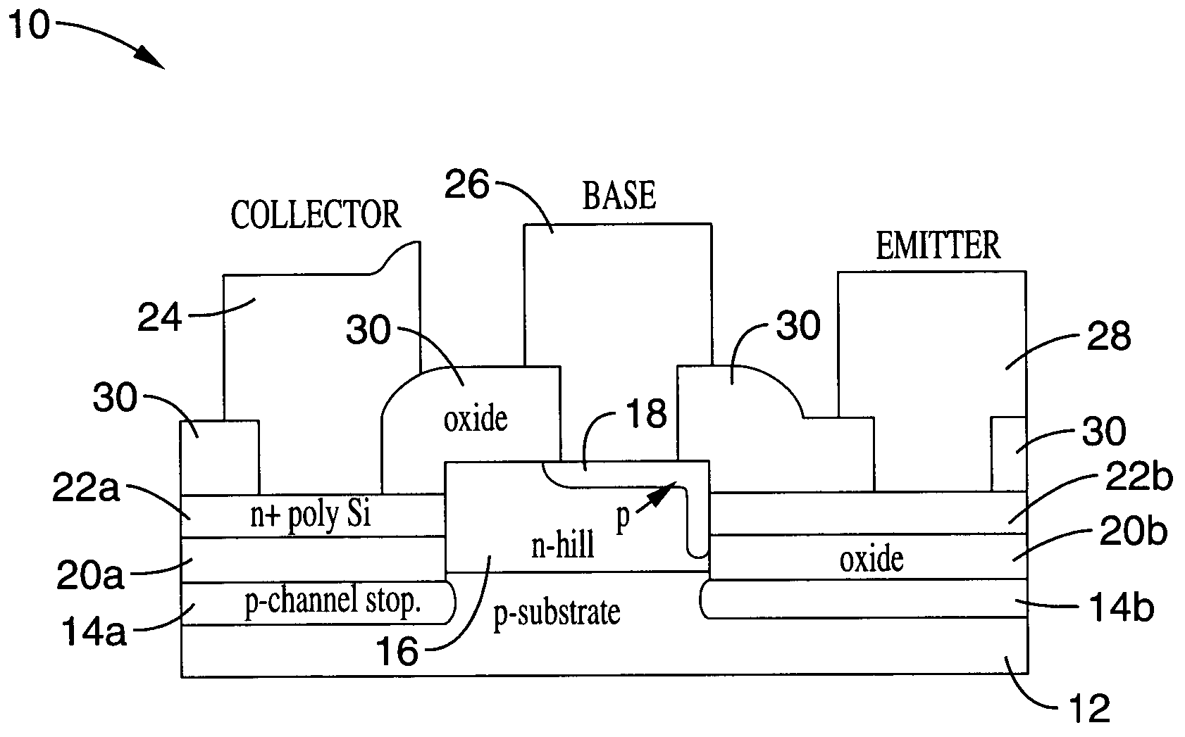
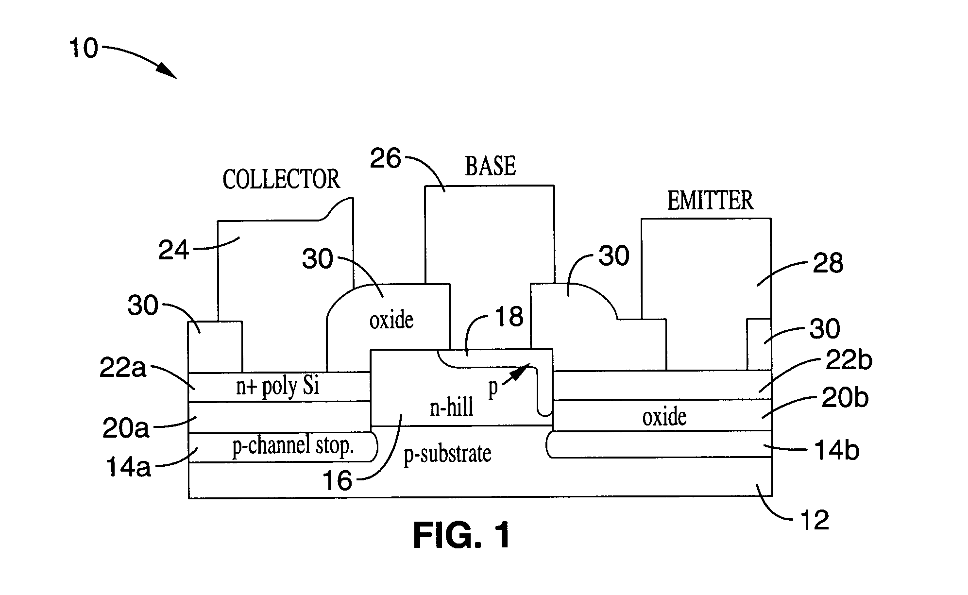
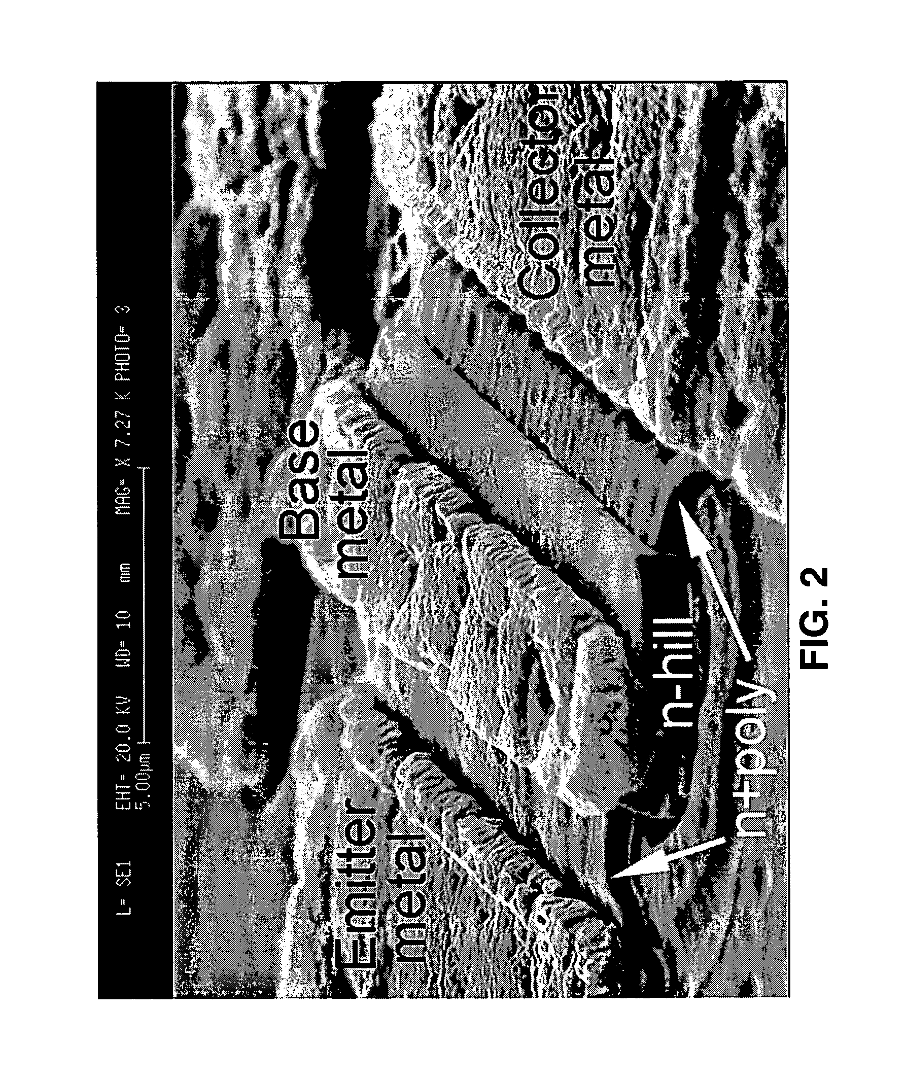
[0024]Referring first to FIG. 1, an embodiment of a Horizontal Current Bipolar Transistor (HCBT) 10 according to the present invention is schematically shown. In the embodiment shown, the device comprises p-type substrate 12, p-channel stoppers 14a, 14b, n-hill 16 with p-region 18, isolation silicon dioxide 20a, 20b, n+ polysilicon 22a, 22b, collector 24, base 26, emitter 28, and surrounding passivation oxide 30. FIG. 2 shows an SEM picture of such an HCBT in 1 μm lithography resolution and provides a perspective view of the device with the passivation oxi...


PUM


Abstract

A bipolar transistor structure for use in integrated circuits where the active device is processed on the sidewall of an n-hill so that the surface footprint does not depend on the desired area of active device region (emitter area). This structure, which is referred to as a Horizontal Current Bipolar Transistor (HCBT), consumes a smaller area of chip surface than conventional devices, thereby enabling higher packing density of devices and / or the reduction of integrated circuit die size. The device is fabricated with a single polysilicon layer, without an epitaxial process, without demanding trench isolation technology, and with reduced thermal budget. Fabrication requires fewer etching processes and thermal oxidations than in conventional devices.

Description

CROSS-REFERENCE TO RELATED APPLICATIONS[0001]This application claims priority to, and is a 35 U.S.C. § 111(a) and 37 C.F.R. § 1.53(b) continuation-in-part of, co-pending PCT international application serial number PCT / US02 / 10402 filed on Apr. 1, 2002 which designates the U.S., incorporated herein by reference in its entirety, and which claims priority to U.S. provisional application Ser. No. 60 / 281,005 filed on Apr. 2, 2001, incorporated herein by reference in its entirety.STATEMENT REGARDING FEDERALLY SPONSORED RESEARCH OR DEVELOPMENT[0002]Not ApplicableREFERENCE TO A COMPUTER PROGRAM APPENDIX[0003]Not ApplicableBACKGROUND OF THE INVENTION[0004]1. Field of the Invention[0005]The present invention pertains generally to bipolar transistor structures, and more particularly to bipolar transistor structures incorporated into integrated circuits.[0006]2. Description of the Background Art[0007]In the current state of the art, mainstream silicon bipolar transistor structures are typically ...

Claims


Application Information

Patent Timeline
Patent Type & Authority Patents(United States)
IPC IPC(8): H01L31/0328H01L21/331H01L29/10H01L29/735
CPCH01L29/1008H01L29/6625H01L29/735
Inventor SULIGOJ, TOMISLAVBILJANOVIC, PETARWANG, KANG L.
Owner RGT UNIV OF CALIFORNIA
Why Eureka
Try Eureka