Electrophoretic display with dual mode switching

a dual-mode switching, electrophoretic display technology, applied in the direction of electric digital data processing, instruments, computing, etc., can solve the problems of poor scratch resistance, difficult problems encountered in partition formation, difficult to form partitions, etc., to achieve high color saturation, low cost, and high contrast

Inactive Publication Date: 2006-05-02
E INK CALIFORNIA
View PDF90 Cites 131 Cited by
  • Summary
  • Abstract
  • Description
  • Claims
  • Application Information

AI Technical Summary

Benefits of technology

[0015]The monochrome EPDs of the present invention are capable of displaying highlight color of choice which is different from the color of the text. For example, white background, blue text, and red highlight can be shown in any selected areas of the display. Furthermore, the full color EPDs of the present invention are capab

Problems solved by technology

However, difficulties are encountered in the formation of the partitions, the process of filling the display with the fluid, enclosing the fluid in the display, and keeping the suspensions of different colors separated from each other.
Even more difficult problems are encountered in the development of a roll-to roll manufacturing process for such a partition type of displays.
The large microcapsule size results in a poor scratch resistance and a slow response time for a given voltage because a large gap between the two opposite electrodes is required for large capsules.
Also, the hydrophilic shell of microcapsules prepared in an aqueous solution typically results in sensitivity to high moisture and temperature conditions.
If the microcapsules are embedded in a large quantity of a polymer matrix to obviate these shortcomings, the use of the matrix results in an even slower response time and/or a lower contrast ratio.
However, the microencapsulation process in aqueous solution imposes a limitation on the type of charge-controlling agents that can be used.
Other drawbacks associated with the microcapsule system include poor resolution and poor addressability for color applications.
The use of microchannels, microgrooves or microcolumns to form

Method used


Image

  • Electrophoretic display with dual mode switching
  • Electrophoretic display with dual mode switching
  • Electrophoretic display with dual mode switching

Examples


Embodiment Construction

[0032]Unless defined otherwise in this specification, all technical terms are used herein according to their conventional definitions as they are commonly used and understood by those of ordinary skill in the art. The terms “well-defined”, “aspect ratio” and “imagewise exposure” are as defined in the co-pending applications identified above.

[0033]It is understood that the scope of the present invention encompasses the conventional EPDs and EPDs manufactured from microcups, microchannels, microcapsules and the like.

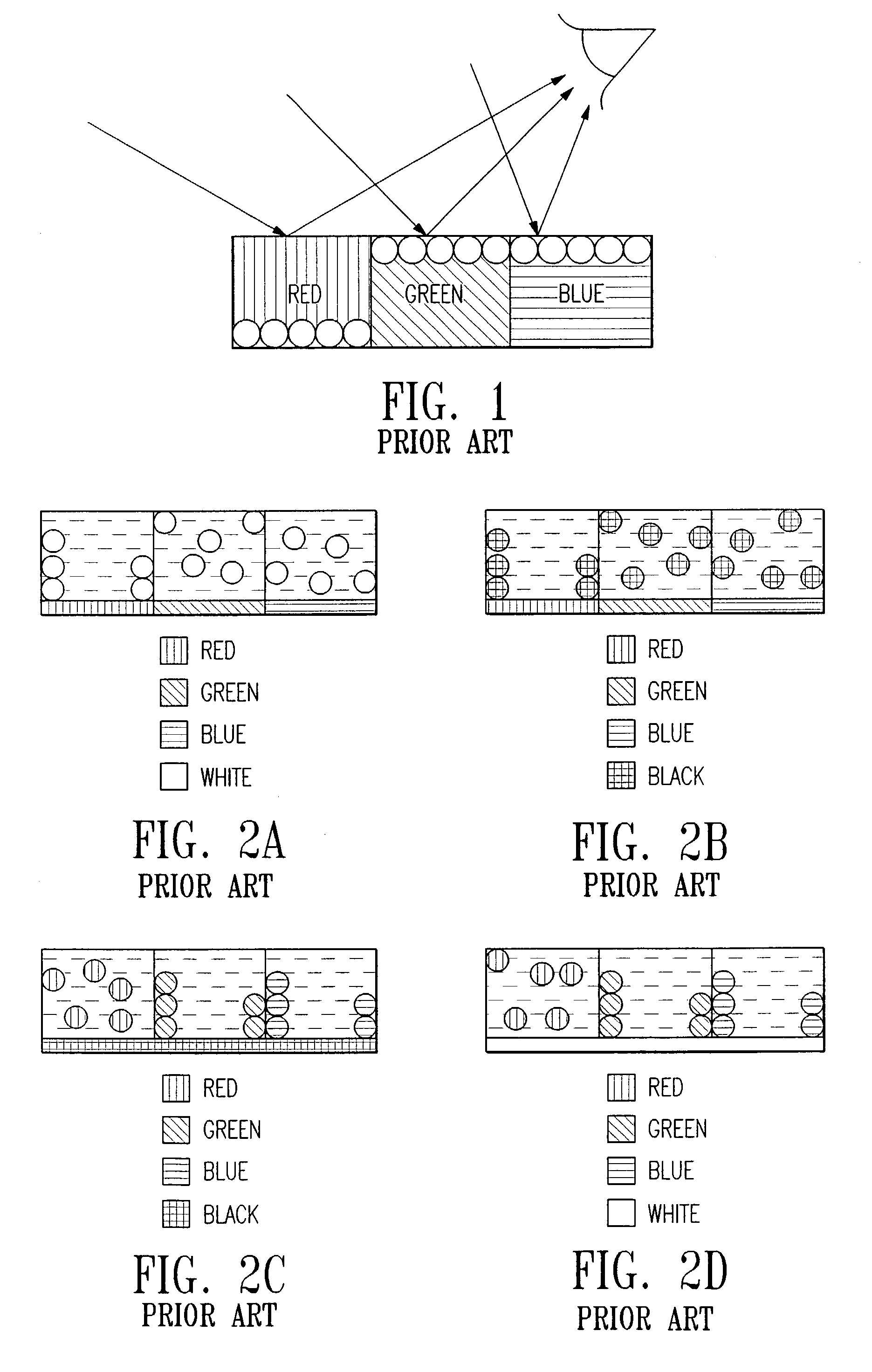
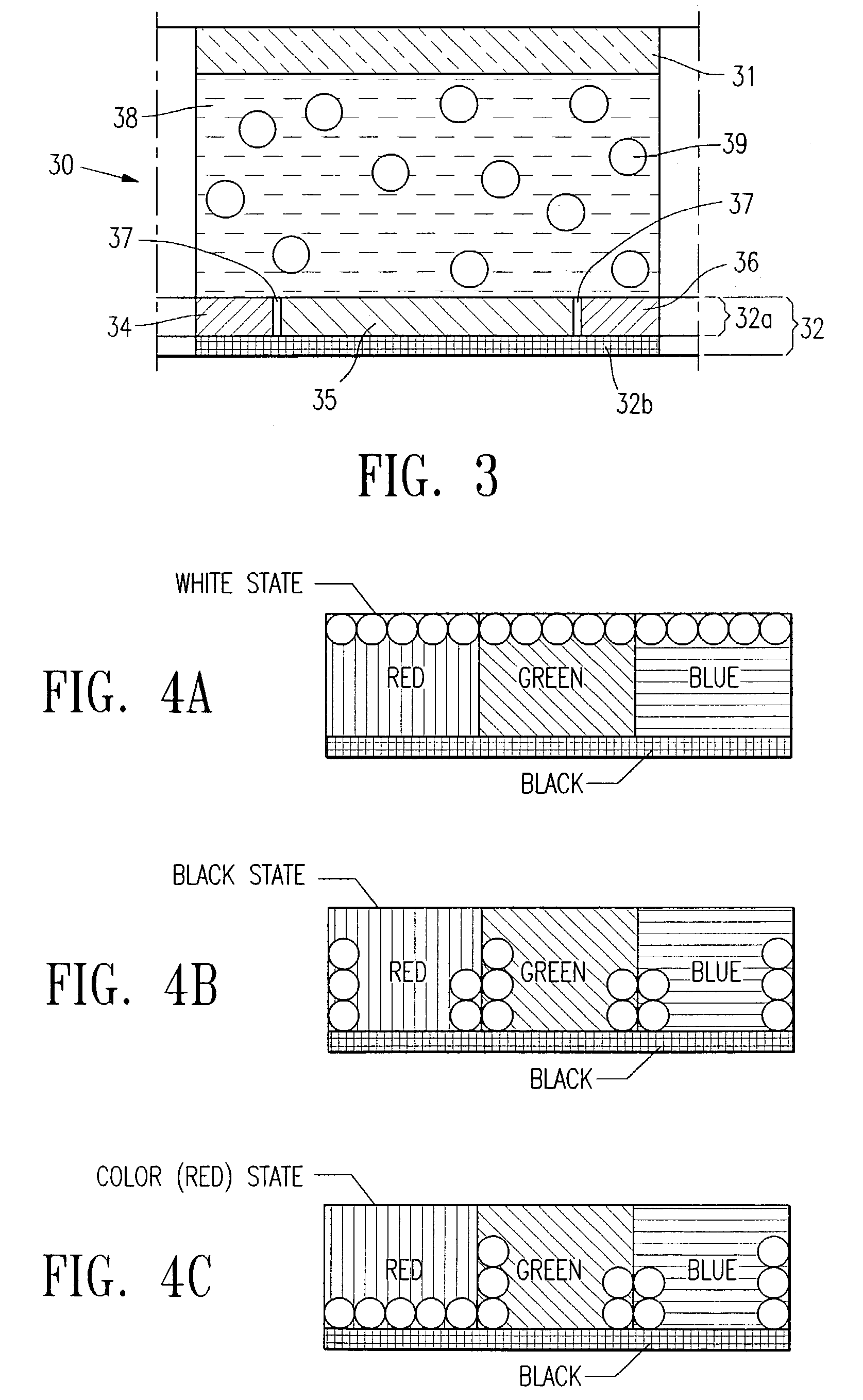
[0034]The term “conventional EPD” refers to any electrophoretic cells known in the art. The electrophoretic cells may be of any shapes and sizes, and the displays include, for example, the partition type displays.

[0035]The term “microchannel” refers to the type of electrophoretic cells disclosed in U.S. Pat. No. 3,612,758.

[0036]The term “microcup” refers to the cup-like indentations, which may be created by methods such as microembossing or imagewise exposure followed by a...


PUM


Abstract

The present invention relates to an improved EPD which comprises both the traditional up/down switching and the in-plane switching modes. The monochrome EPDs of the present invention are capable of displaying highlight color of choice which is different from the text. For example, white background, blue text, and red highlight can be shown in any selected areas of the display. Furthermore, the full color EPDs of the present invention are capable of displaying high contrast images of high color saturation. Both high quality black and white states are possible in the full color displays of the present invention. The EPDs of the present invention do not need complex circuitry design, and are compatible with low cost and high yield roll-to-roll manufacturing processes. The EPD cells of the present invention may have opaque partition walls, or a black matrix top surface of the partition walls or a combination thereof.

Description

CROSS-REFERENCE TO RELATED APPLICATION[0001]This is a continuation-in-part application of U.S. patent application Ser. No. 10 / 222,036 filed on Aug. 16, 2002, the content of which is incorporated herein by reference in its entirety.BACKGROUND OF THE INVENTION[0002]The electrophoretic display (EPD) is a non-emissive device based on the electrophoresis phenomenon influencing charged pigment particles suspended in a solvent. This general type of display was first proposed in 1969. An EPD typically comprises a pair of opposed, spaced-apart and plate-like electrodes, with spacers predetermining a certain distance between the electrodes. At least one of the electrodes, typically on the viewing side, is transparent. For the passive type of EPDs, row and column electrodes on the top (the viewing side) and bottom plates respectively are needed to drive the displays. In contrast, an array of thin film transistors (TFT) on the bottom plate and a non-patterned transparent conductor plate on the ...

Claims


Application Information

Patent Timeline
IPC IPC(8): G09G5/00G02F1/167G02F1/16762G02F1/1677G09G3/34
CPCG02F1/167G09G3/344G02F1/134363G02F2001/1672G02F2001/1676G09G2320/0252G09G2300/06G09G2300/08G09G2310/0262G09G2320/02G09G2300/0426G02F1/1681G02F1/1677G02F1/16762
Inventor LIANG, RONG-CHANGCHUNG, JERRY
Owner E INK CALIFORNIA
Why Eureka
Try Eureka