X-ray microscope apparatus

a microscope and x-ray technology, applied in the field of x-ray microscope equipment, can solve the problems of low condensing efficiency of x-ray imaging device, large overall length of x-ray microscope, and low focal length of x-ray magnification optical system, and achieve the effect of small size and convenient us

Inactive Publication Date: 2006-05-02
KAWASAKI HEAVY IND LTD
View PDF24 Cites 32 Cited by
  • Summary
  • Abstract
  • Description
  • Claims
  • Application Information

AI Technical Summary

Benefits of technology

[0010]Accordingly, it is an object of the present invention to provide an X-ray microscope apparatus using a contact imaging method capable of forming sharp X-ray images, having a small size and easy to use.

Problems solved by technology

Since the X-ray imaging device has low converging power, the focal length of an X-ray magnification optical system is inevitably long and hence the X-ray microscope has a big overall length.
Although the resolution of the most advanced zone plate system is 50 nm, the zone plate system needs a light source capable of emitting intense light, such as synchrotron radiation, because the condensing efficiency of the X-ray imaging device is low.
Since it is difficult to provide an X-ray imaging device with a zooming function that enables magnification adjustment, another image enlarging device, such as an optical microscope, must be used in combination with the X-ray imaging device to specify the observation position of the object, which requires troublesome operations.
The projection enlargement method inevitably involves penumbral blurring due to the size of the X-ray source and diffraction blurring due to the specimen.
The observation of an enlarged X-ray image needs troublesome operations for taking the photoresist plate out of a vacuum vessel, forming an X-ray image by a developing process, and enlarging the developed X-ray image by an optical microscope or the like for observation.
Since the vacuum of the vacuum vessel needs to be broken in taking the photoresist plate out of the vacuum vessel, many X-ray images cannot continuously be obtained.

Method used


Image

  • X-ray microscope apparatus
  • X-ray microscope apparatus
  • X-ray microscope apparatus

Examples


first embodiment

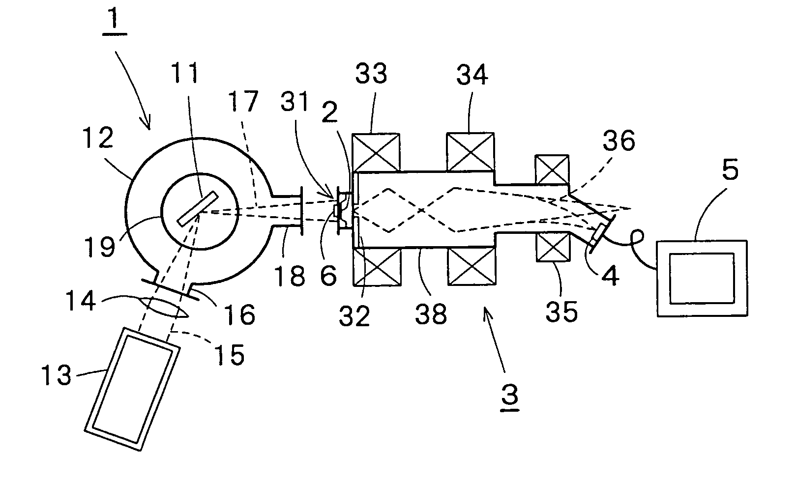
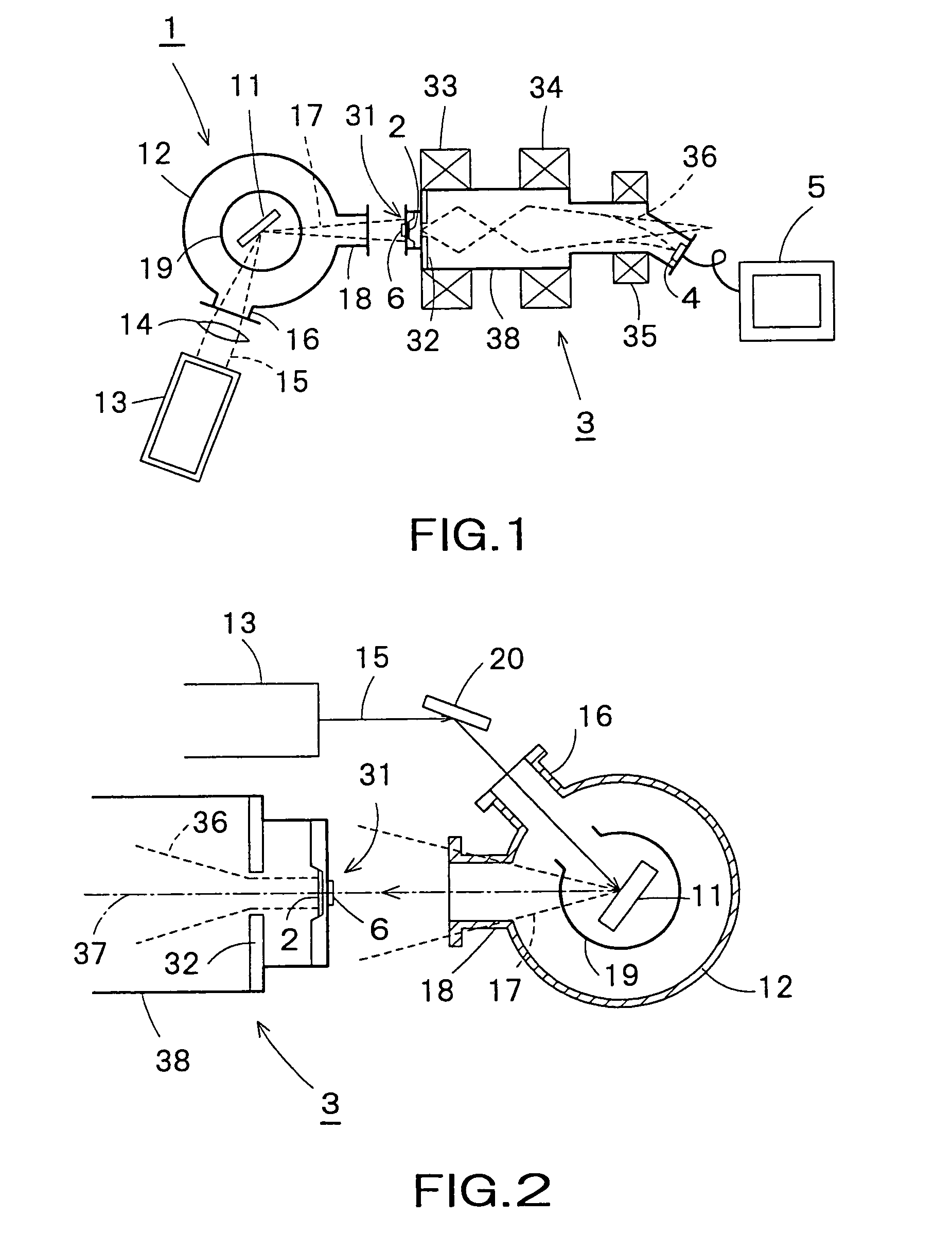
[0036]Referring to FIG. 1, an X-ray microscope apparatus in a first embodiment according to the present invention includes an X-ray generator 1, a photocathode 2, an electron image enlarging device 3, an electron beam detecting device 4 and an image processing device 5.

[0037]The X-ray generator 1 includes a vacuum vessel 12 defining a vacuum chamber for holding a target 11 of a metal therein, a laser 13, and a condenser lens 14. The condenser lens condenses a laser beam 15 emitted by the laser 13. The condensed laser beam 15 travels through an inlet nozzle 16 attached to the vacuum vessel 12 onto the vacuum chamber and falls on a surface of the target 11. The metal forming the target 11 is heated rapidly into a plasma and thereby X-rays 17 are generated.

[0038]The target 11 may be surrounded by a target cover 19 to prevent metal particles from scattering and adhering to the inner surface of the vacuum vessel 12. The target cover 19 must be formed of a material transparent to X-rays, ...

second embodiment

[0050]As shown in FIG. 2, in the X-ray microscope apparatus the laser 13 and the electron image enlarging device 3 are disposed such that the axis of a laser beam 15 emitted by the laser 13 and the axis 37 of an electron beam 36 in the electron image enlarging device 3 are parallel. An incident angle adjusting mirror 20 is disposed between the laser 13 and an entrance nozzle 16 formed on the vacuum vessel 12. The incident angle adjusting mirror 20 reflects the laser beam 15 emitted by the laser 13 toward the metal target 11.

[0051]Even though the laser 13 and the electron image enlarging device 3 are disposed such that the axis of the laser beam 15 emitted by the laser 13 and the axis 37 of the electron beam 36 in the electron image enlarging device 3 are parallel, a sharp X-ray image can be formed by adjusting the position of the incident angle adjusting mirror so that the laser beam 15 falls at a predetermined incident angle on the metal target 11, because a specimen 6 attached to...


PUM

PropertyMeasurementUnit
wavelengthsaaaaaaaaaa
distanceaaaaaaaaaa
wavelengthsaaaaaaaaaa

Abstract

An X-ray microscope apparatus includes an X-ray generator, a photocathode disposed on a path of X-rays for producing electrons when irradiated with X-rays generated by the X-ray generator, an electron image enlarging device having an acceleration anode for accelerating electrons produced by the photocathode and a magnetic lens for enlarging and focusing an electron beam of electrons emitted by the photocathode, an electron beam detecting device for detecting the electron beam focused thereon by the electron image enlarging device; and an image processing device for processing an electron image formed by the electron beam detecting device. The X-ray microscope apparatus can be formed in compact construction.

Description

BACKGROUND OF THE INVENTION[0001]1. Field of the Invention[0002]The present invention relates to an X-ray microscope apparatus and, more particularly, to an X-ray microscope apparatus capable of forming an enlarged X-ray image of a specimen held in contact condition.[0003]2. Description of the Related Art[0004]Some of X-ray microscopes that form a high-resolution transmission image of an object by using X-rays of short wavelengths having high penetrating power use an X-ray imaging device and the others do not. X-ray imaging devices include Fresnel zone plates, grazing incidence mirrors, etc. Since the X-ray imaging device has low converging power, the focal length of an X-ray magnification optical system is inevitably long and hence the X-ray microscope has a big overall length. Although the resolution of the most advanced zone plate system is 50 nm, the zone plate system needs a light source capable of emitting intense light, such as synchrotron radiation, because the condensing ef...

Claims


Application Information

Patent Timeline
Patent Type & Authority Patents(United States)
IPC IPC(8): G21K7/00G01N23/04G21K5/08H01J31/50
CPCG21K7/00
Inventor FUJII, SADAOMURO, MIKIOSATO, EIJI
Owner KAWASAKI HEAVY IND LTD
Why Eureka
Try Eureka