
Connection structure between bus bars and relay terminals

Inactive Publication Date: 2006-05-09
SUMITOMO WIRING SYST LTD
View PDF8 Cites 6 Cited by
  • Summary
  • Abstract
  • Description
  • Claims
  • Application Information

AI Technical Summary

Benefits of technology

[0010]In view of the above problems, it is an object of the present invention to provide a connection structure between bus bars and relay terminals that enhances automobile recyclability, electrical connection reliability and prevents electric erosion.
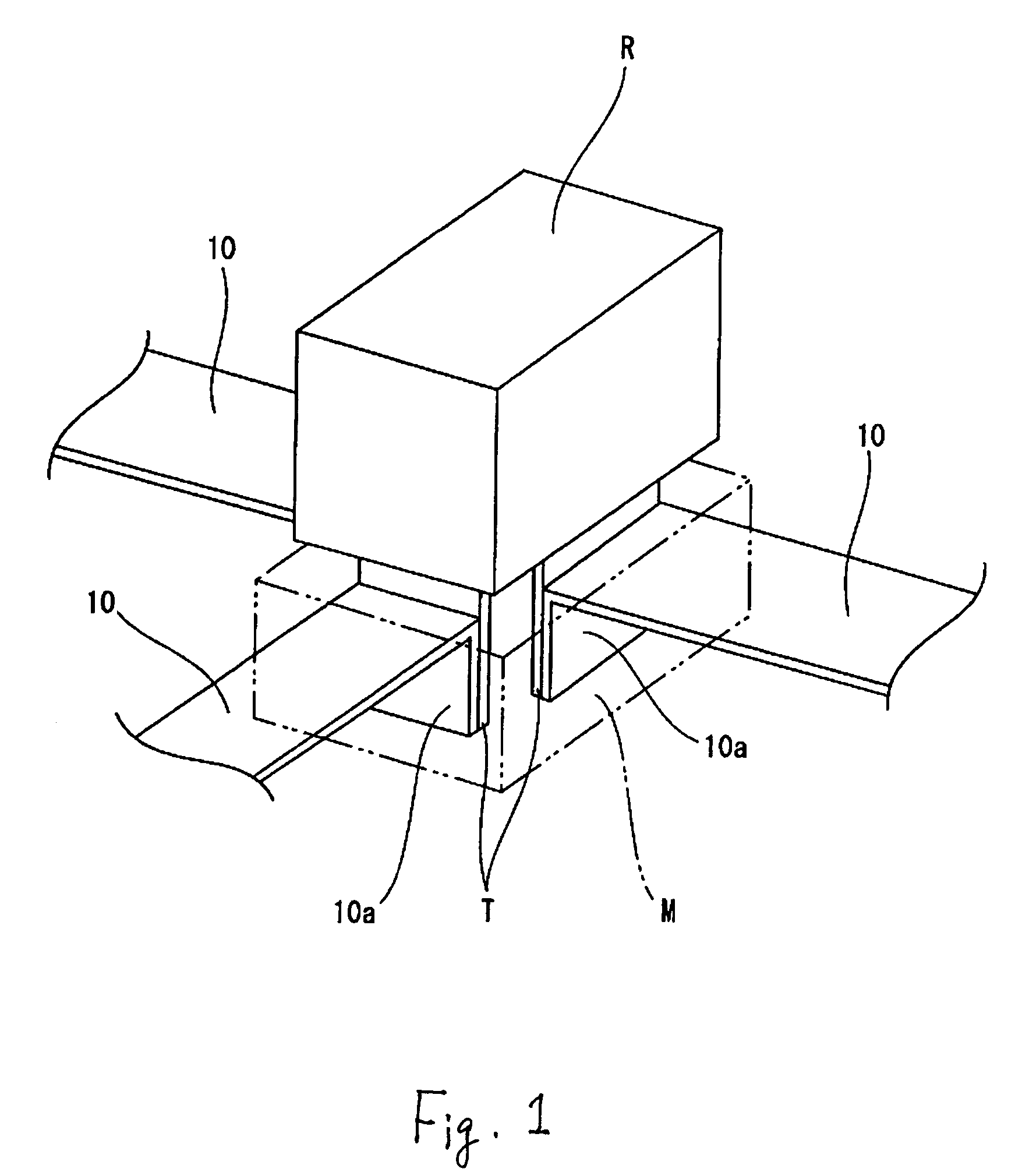
[0012]According to the above structure, since the bus bars, made of the aluminum-based metal, are provided in lieu of conventional bus bars made of a copper-based metal, it is possible to reduce the copper to iron mixing rate which influences the iron-recovery during recycling of car bodies and enhances recyclability of junked automobile.
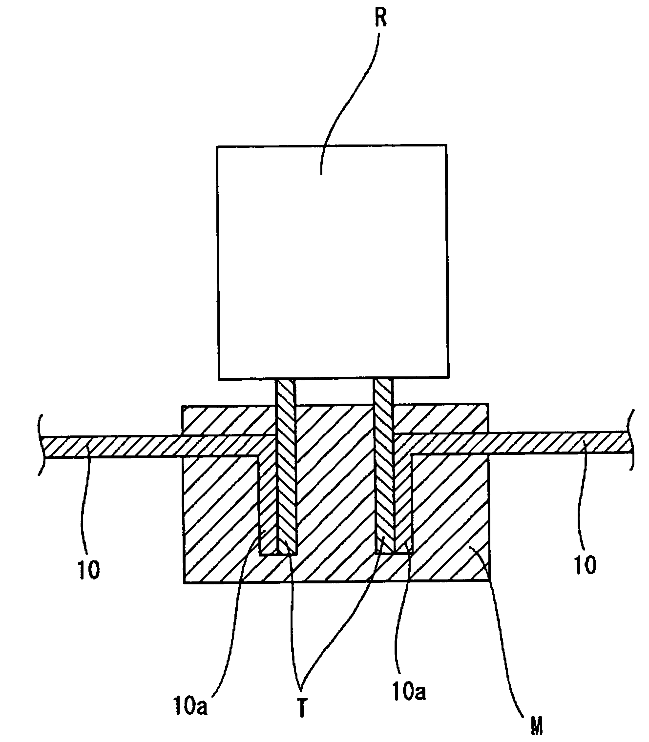
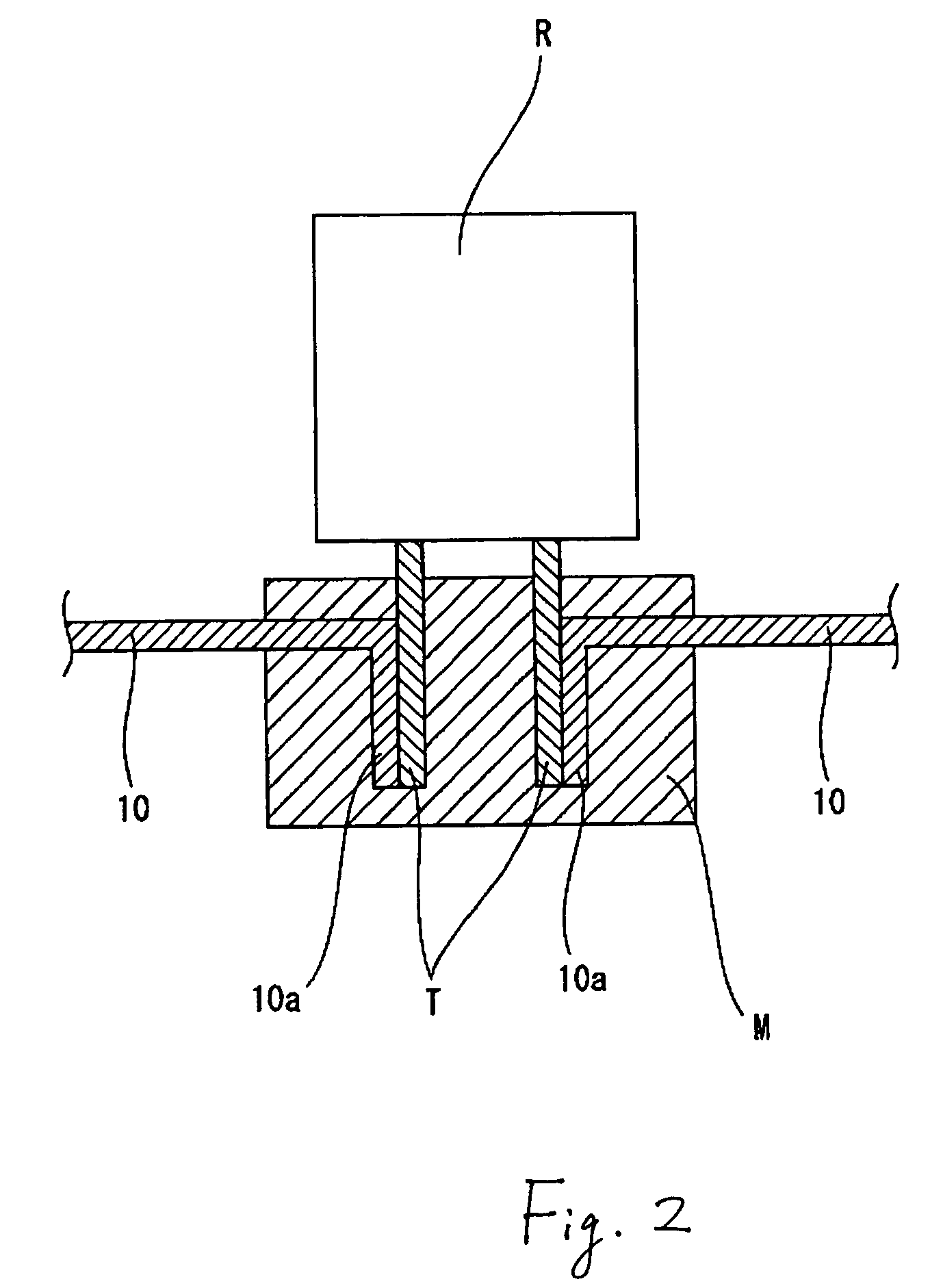
[0014]Furthermore, since the connection parts are embedded in the molded insulation resin, it is possible to prevent water from infiltrating the connection parts between the bus bars and the relay terminals. Accordingly, even if the connection parts are made of different kinds of metal, it is possible to prevent electric erosion.
[0015]Since aluminum does not react to denature an iron-based metal, which is a main material of a car body, it is possible to enhance recovery of the iron-based metal. In addition, the aluminum-based bus bars have rust-resistance characteristics, good workability, and provide a lightweight electrical connection box.
[0017]The above structure provides the same effect as in the case where the connection parts are in the molded insulation resin. Since a method for filling and applying grease to the connection parts does not require a mold, it is possible to embed the connection parts at a cost lower than molded resin.

Problems solved by technology

This work requires extensive manpower and is not practical.
However, since aluminum-based metal is low in hardness and stiffness, a mating relay terminal T tends to widen the tab 4a′ provided with a press contact slot, as shown in FIG. 4.
This lowers the reliability of the electrical connection.
Also, a connection part between the bus bar 4′, made of the aluminum-based metal, and the relay terminal T, made of the copper-based metal, will suffer from electric erosion if any water infiltrates the connection part.

Method used


Image

  • Connection structure between bus bars and relay terminals
  • Connection structure between bus bars and relay terminals
  • Connection structure between bus bars and relay terminals

Examples


Embodiment Construction

[0024]Embodiments of a connection structure between bus bars and relay terminals in accordance with the present invention will be described below.

[0025]FIGS. 1 and 2 show an embodiment of the connection structure in accordance with the present invention. Bus bars 10 shown in FIG. 1 are disposed on insulation plates 3 as internal circuits in the electrical connection box 1 for an automobile, shown in FIG. 3. Each bus bar 10 includes a flat plate circuit body produced by punching an aluminum plate in desired circuit configurations. An end of each flat plate circuit body is bent down to form a tab 10a. The bus bar 10 may be made of not only pure aluminum but also an aluminum alloy, such as Al—Mg, Al—Mn, Al—Mg—Si, Al—Zn—Mg, Al—Si, or the like. Conductivity of pure aluminum is 60% of that of copper while conductivity of an aluminum alloy is 30% of copper. It is thus preferable to use pure aluminum from a conductivity standpoint.

[0026]Three relay terminals T made from brass having a coppe...


PUM


Abstract

A connection structure is between bus bars and relay terminals in an electrical connection box to be mounted on an automobile. Each bus bar is produced by punching an aluminum-based metal plate into a desired circuit configuration. An end of each bus bar is bent so that the end is connected to each respective relay terminal. Each bus bar end is welded to the respective relay terminal. Connection parts between the bus bars and the relay terminals are embedded in a molded insulation. Alternatively, grease is applied to and fills in exteriors and clearances of the connection parts.

Description

CROSS-REFERENCE TO RELATED APPLICATIONS[0001]The entire disclosure of Japanese Patent Application No. 2002-256346 filed on Sep. 2, 2002 including the specification, claims, drawings and summary is incorporated herein by reference in its entirety.FIELD OF THE INVENTION[0002]The present invention relates to a connection structure between bus bars and relay terminals. More particularly, the invention relates to bus bars made of a recyclable material that are arranged as internal circuits in an electrical connection box, such as a junction box or the like, to be mounted on an automobile.BACKGROUND OF THE INVENTION[0003]Heretofore, bus bars, produced by punching an electrical conductive material, are contained as internal circuits in an electrical connection box such as a junction box or the like.[0004]For convenience of explanation, a conventional connection structure between bus bars and relay terminals will be described by referring to FIG. 3. FIG. 3 is an exploded perspective view of...

Claims


Application Information

Patent Timeline
IPC IPC(8): H01R12/00B60R16/02H01R4/02H01R4/70H01R43/02H02G3/16H05K3/20H05K3/32
CPCH01R4/029H05K3/328H01R4/70H01R43/0214H01R2201/26H05K3/202Y10S439/936H05K2201/0397H05K2201/10053H05K2201/10977H05K2203/1316
Inventor YAMAKAWA, SHUJIYUASA, ERIKO
Owner SUMITOMO WIRING SYST LTD
Learn More