Heat transfer pipe and heat exchange incorporating such heat transfer pipe

a technology of heat transfer pipe and heat exchanger, which is applied in the direction of indirect heat exchanger, light and heating apparatus, laminated elements, etc., can solve the problems of reducing the workability of heat conductor pipe, reducing the thermal conductivity of low-energy coatings such as fluoric resin, and reducing the thermal conduction efficiency. , to achieve the effect of not reducing the thermal conduction efficiency

Inactive Publication Date: 2006-05-16
USUI KOKUSAI SANGYO KAISHA LTD
View PDF11 Cites 54 Cited by
  • Summary
  • Abstract
  • Description
  • Claims
  • Application Information

AI Technical Summary

Benefits of technology

[0008]This invention is to solve the above problems. It is an object of the invention to provide a heat conduction pipe removing soot deposited thereon or preventing the soot deposition without reducing a thermal conduction efficiency as a primary object of the heat conduction pipe, neither stopping cooling operation in the heat conduction pipe. This invention also provides a heat conduction pipe minimizing reduction of the thermal conduction rate thereof for the soot and capable of forming the heat conduction pipe having large heat exchange surface by removing the soot while the soot deposits slightly on the inner surface of the heat conductive pipe, or by preventing the soot from depositing. Therefore, the thermal exchange between a liquid flowing through the interior of the heat conduction pipe and a liquid flowing through the exterior heat conduction pipe can be performed at the all times.

Problems solved by technology

Where the soot deposits on the inner surface of the heat conduction, the soot creates a heat insulation effect to reduce a thermal conduction efficiency, so that it is undesirable as diminishing functions in terms of the heat conduction pipe.
However, with the method for wiping the soot off using the blush or the other, or for heating the heat conduction pipe to bum the soot by stopping a cooling operation therein, the workability of the heat conductor pipe may be significantly reduced, not only because many processing steps are needed but also because the cooling operation in the heat conductor pipe has to be stopped.
However, with the method for forming the low energy coating on the inner surface of the heat conduction pipe, the thermal conduction rate and the thermal conductivity of the low energy coating such as fluoric resin are low compared to metal, so that the thermal conduction efficiency of the heat conduction pipe as of essentially a heat exchanger may be reduced.

Method used


Image

  • Heat transfer pipe and heat exchange incorporating such heat transfer pipe
  • Heat transfer pipe and heat exchange incorporating such heat transfer pipe
  • Heat transfer pipe and heat exchange incorporating such heat transfer pipe

Examples


first embodiment

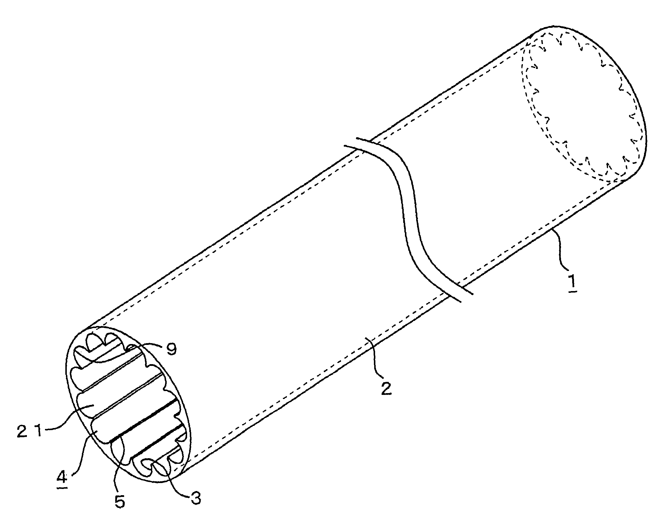
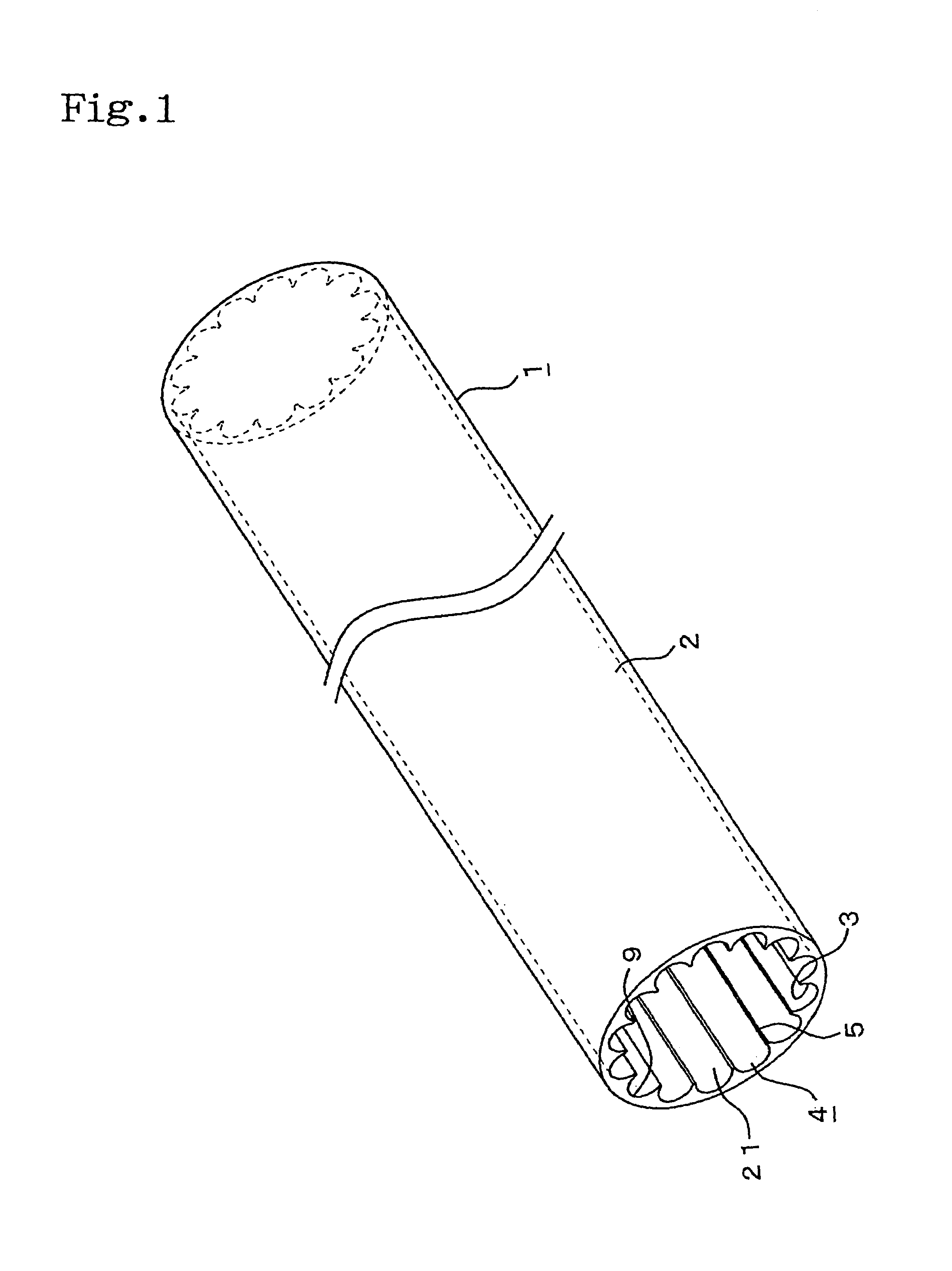
[0047]Hereinafter, according to a heat conductive pipe of this invention, the first embodiment in which the heat conductive pipe an EGR gas cooling apparatus is used in a cooled EGR system for automobiles is described in reference to FIG. 1, FIG. 2, and FIG. 3. Numeral 1 is the heat conductive pipe wherein axially extending grooves having a cross section perpendicular to a direction of the pipe axis defined recesses 3 in a shape with a prescribed depth on an inner circumferential surface of a base pipe 2.

[0048]The axially extending grooves 4 are formed parallel to a pipe axis in a row in a circumferential direction of the heat conductive pipe 1. The axially extending grooves 4 in a row form dividing walls 5 with a prescribed thickness dividing between themselves. According to the first embodiment, bottom portions 9 of the axially extending groove 4 and the dividing wall 5 are formed running in a circular shape, thereby forming a cross section of the recess 3 in a substantially semic...

second embodiment

[0057]Furthermore, in the second embodiment, as shown in FIG. 4 and FIG. 5, the plurality of the axially extending grooves 4 having a cross section in a recess 3 shape perpendicular to the direction of the pipe axis with the prescribed depth are formed parallel to the pipe axis in a row not only on the inner circumferential surface of the base pipe 2 but also on each of the surfaces of the plate-shaped fin member 18. Furthermore, a dividing wall 5 having a prescribed thickness partitioning the axially extending grooves 4 adjacent to each other in a row is formed thereon.

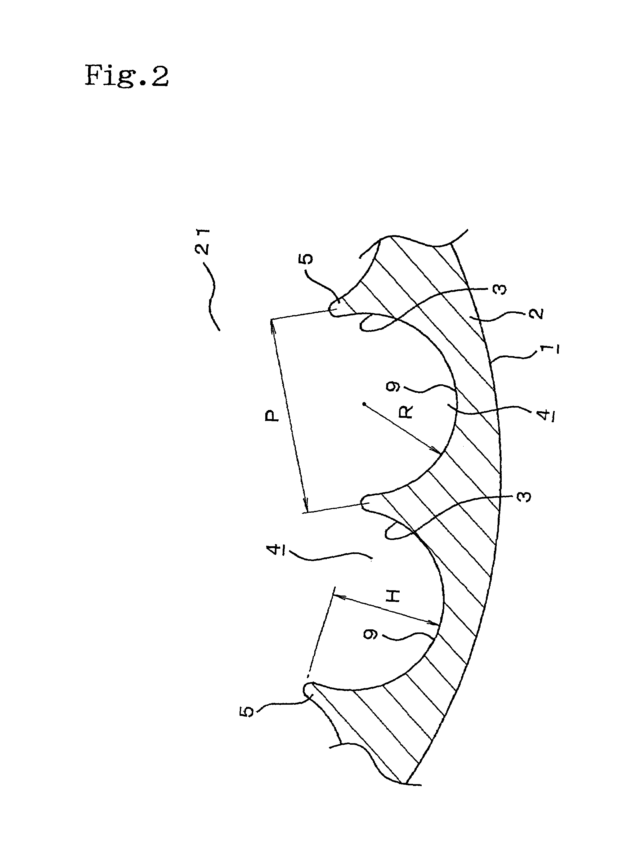
[0058]As shown FIG. 2 and FIG. 5, in the axially extending grooves 4 formed on the inner circumferential surface of said base pipe 2 and on each of the surfaces of the plate-shaped fin member 18, distance P between the centers of the dividing walls 5 next to each other is defined from 0.2 to 2.0 mm, and distance H from the top of the dividing wall 5 is defined from 0.5 P to 1.0 P mm. Furthermore, radius R of the rece...

third embodiment

[0062]Also, in the third embodiment, though the plurality of the axially-extending grooves 4 having the cross section in the circularly recess 3 shape with the prescribed thickness are formed in a row on the inner circumferential surface, of the base pipe 2 and each of the surfaces of the plate-shaped fin member 18, the connecting surfaces 19 of the plate-shaped fin member 18 and the portions to be connected to the connecting surfaces 19 of the inner circumferential surface of the base pipe 2 are formed without forming the axially extending grooves 4, thereby enlarging the contacted area to allow the thermal conductivity between the base pipe 2 and the plate-shaped fin member 18 to be performed well.

[0063]However, the axially extending grooves 4 may be formed on the connecting surfaces 19 of the plate-shaped fin members 18 and on the inner circumferential surface of the base pipe 2 all over, thereby arising gaps between the connecting surfaces 19 and the inner circumferential surfac...


PUM

PropertyMeasurementUnit
depthaaaaaaaaaa
distanceaaaaaaaaaa
distanceaaaaaaaaaa

Abstract

Soot adhering to the inner surface of a heat transfer pipe can be removed without lowering the heat transfer efficiency that is the inherent object of the heat transfer pipe or without stopping the cooling operation of the heat transfer pipe. Further, this soot removal can be effected when the amount of soot adhering to the inner surface of the heat transfer pipe is small, thus minimizing the soot-caused lowering in the heat transfer efficiency of the heat transfer pipe. A heat transfer pipe (1) wherein the inner peripheral surface of an element pipe (2) through which fluid can flow is formed with longitudinal grooves (4) as recessed grooves (3) of cross-section with a given depth such that the longitudinal grooves are parallel with the pipe axis and circumferentially continuous, and a partition wall (5) of given thickness is formed between the longitudinal grooves (4): and a heat exchanger incorporating this heat transfer pipe (1).

Description

BACKGROUND OF THE INVENTION[0001]1. Field of the Invention[0002]This invention relates to a heat conduction pipe and a heat exchanger assembled with said heat conduction pipes for performing thermal exchange between cooling water, cooling air, cooling medium for air conditioner, or other cooling mediums and EGR gas (Exhaust Gas Recirculation) gas or combustion exhaust gas including soot in a mulitube heat exchanger such as an EGR cooling mechanism and so on.[0003]2. Description of Related Art[0004]Conventionally, EGR systems in which a part of exhaust gas is taken out of an exhaust gas system and returned to an intake system of the engine to be added to the mixture gas and the intake air, have been used in engines for automobiles along with gasoline engines and diesel engines. With the EGR system, particularly with the cooled EGR system for diesel engines of high EGR rate, a cooling apparatus for cooling the EGR gas at a high temperature with cooling water, cooling air, refrigerants...

Claims


Application Information

Patent Timeline
Patent Type & Authority Patents(United States)
IPC IPC(8): F28F1/40F28D7/16F28F1/00F28F3/02
CPCF28D7/1607F28F1/00F28F3/025F28F1/40F28F1/022F28F2215/10
Inventor USUI, SHOUICHIRO
Owner USUI KOKUSAI SANGYO KAISHA LTD
Why Eureka
Try Eureka