Method for drilling with casing

a wellbore and casing technology, applied in the direction of drilling pipes, drilling well accessories, directional drilling, etc., can solve the problems of difficult control of the well, time-consuming and costly running of casing into the borehole, and pulling out the drill pipe, so as to reduce the risk of a cave-in and the effect of increasing the chance of a cave-in

Inactive Publication Date: 2006-05-16
SCHLUMBERGER TECH CORP
View PDF14 Cites 90 Cited by
  • Summary
  • Abstract
  • Description
  • Claims
  • Application Information

AI Technical Summary

Benefits of technology

[0014]In wellbore drilling it is preferable that fluid circulation be maintained even during periods in which the drill bit is not operating. Fluid circulation acts to condition the well, remove debris and prevent cave in. Therefore, in a preferred aspect of the present invention the disengagement of the drilling assembly from the drill string is carried out using a means that permits circulation during the actuation operation. Further, the chances of a cave-in increase with increased time between stopping the drilling operation and advancing the casing. Therefore, a process is preferred wherein the step of disengaging to initiate the advancement of the drill string is minimised with respect to time required. In other words, a process for releasing the drilling assembly from engagement with the drill string is preferred that minimises time taken. Since the use of a work string requires that the work string be fully removed from the casing before further joints of casing, or drill pipe in the case of liner drilling, can be added to advance the drill string, any process that uses a work string inserted through the casing requires more time than one not using an inserted work string. Thus, a process is preferred wherein the step of disengagement is accomplished without the use of a work string. These processes permit continued circulation during actuation of release of the drilling assembly from the drill string. In addition, these processes do not require a delay between release of the drilling assembly from the drill string and advancement of the drill string over the drilling assembly. The step of disengagement can include for example, releasing a fluid or gravity conveyed tool such as a ball, spear, a drop bar or a fluid-conveyed dart or actuation by a mud pulse, or electromagnetic or electrical actuation. A ball can be dropped where the wellbore is substantially vertical. Where the wellbore contains some deviations, the use of a fluid-conveyed dart is preferred. The use of a mud pulse, electrical signal or an electromagnetic signal can be used but will require the use of a drilling assembly which can recognize the signal to disengage.

Problems solved by technology

This conventional system which requires sequentially drilling the borehole using drill pipe with a drill bit attached thereto, pulling the drill pipe out of the borehole and running casing into the borehole is time consuming and costly.
In addition, control of the well is difficult during the period that the drill pipe is being removed and the casing is being run in.
Thus, during the drilling process the distal end of the casing does not extend fully to the bottom of the well.
This process has experienced considerable difficulties.
The borehole can also cave-in in the intervening period between removing the bottom hole assemblies and attempting to move the casing downhole.
The problems increase with increased time delay between stopping drilling and advancing the casing.
Similar problems have been experienced in another form of casing drilling, more commonly termed liner drilling.

Method used


Image

  • Method for drilling with casing
  • Method for drilling with casing
  • Method for drilling with casing

Examples


Embodiment Construction

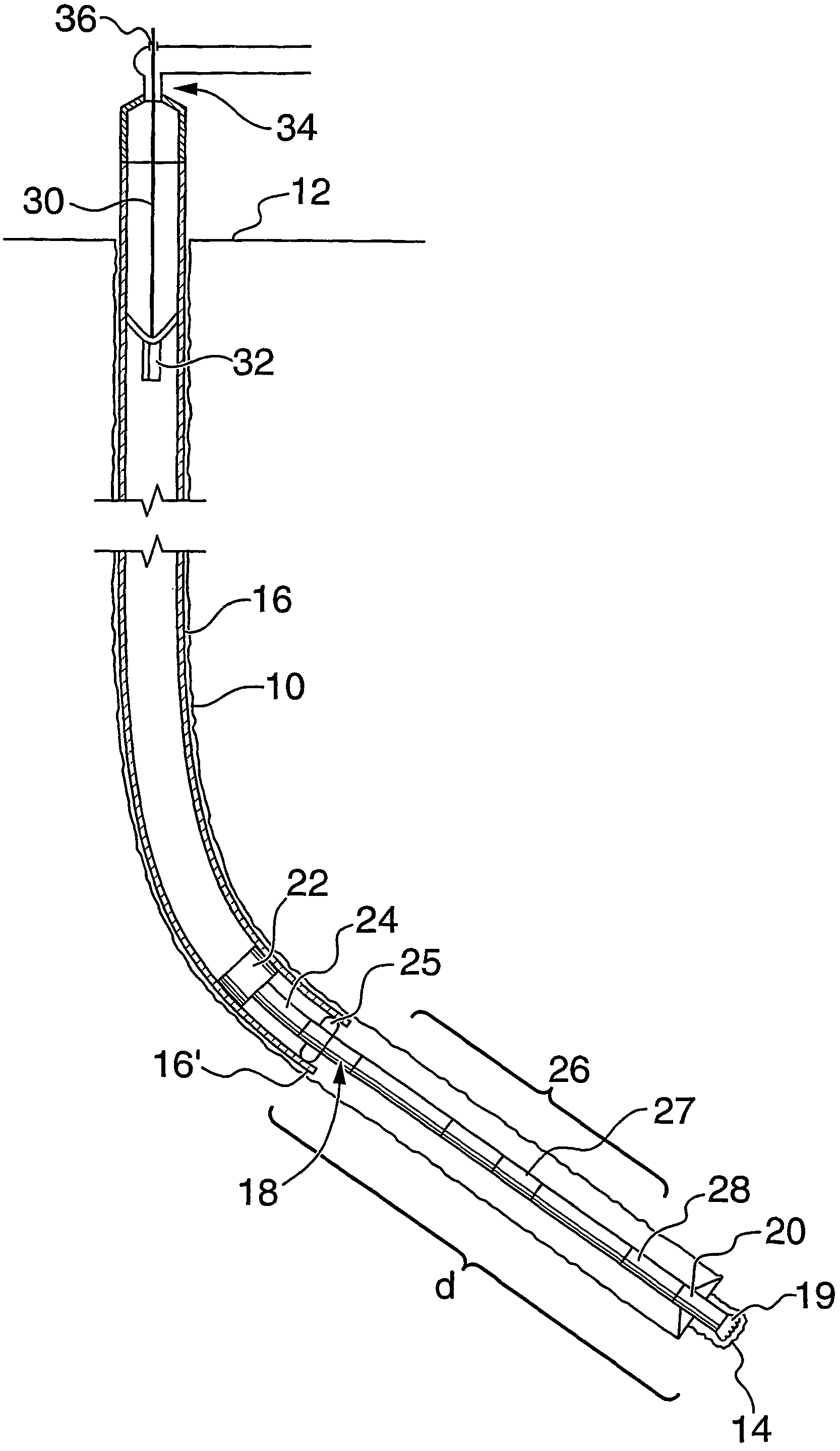
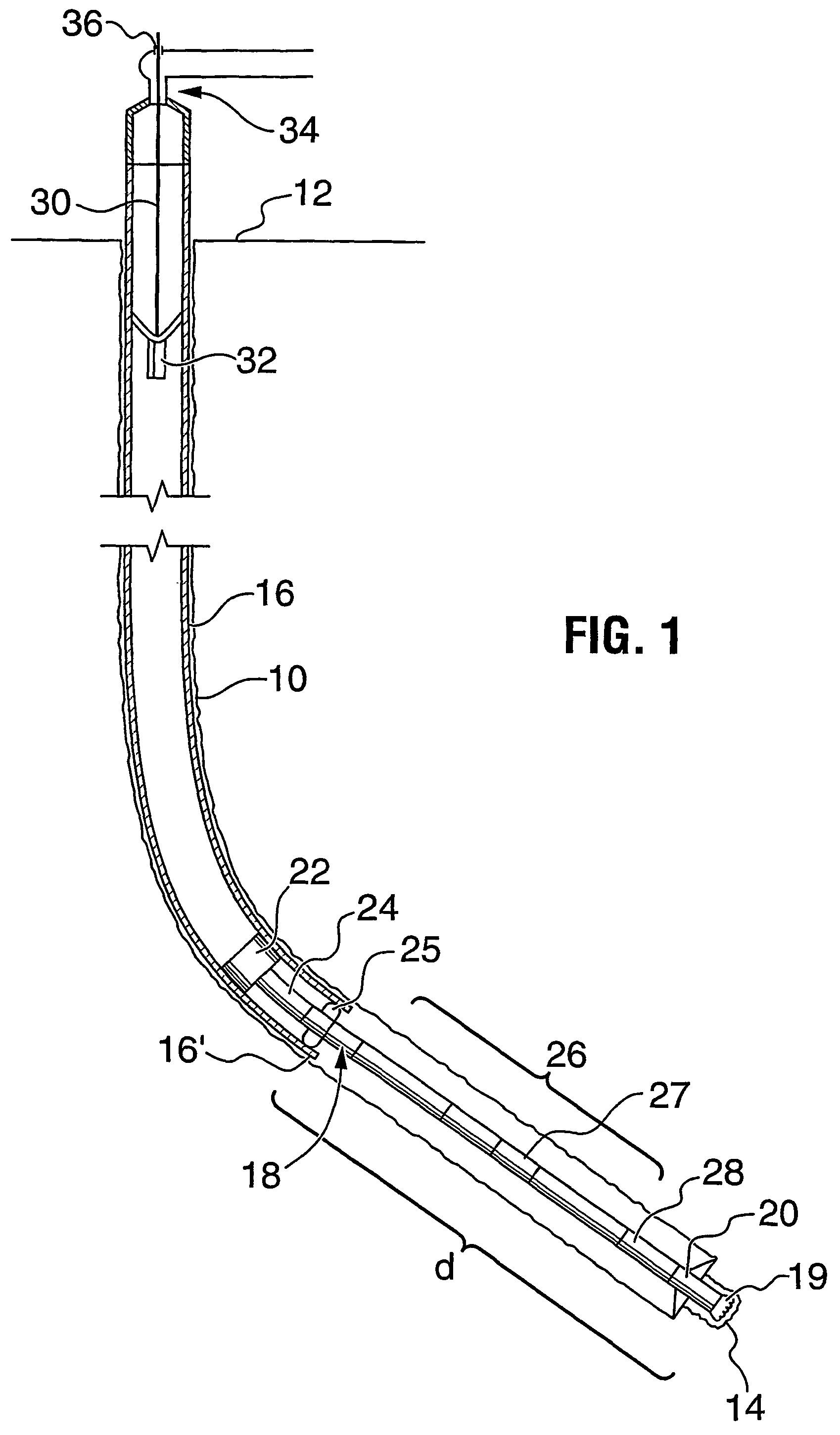
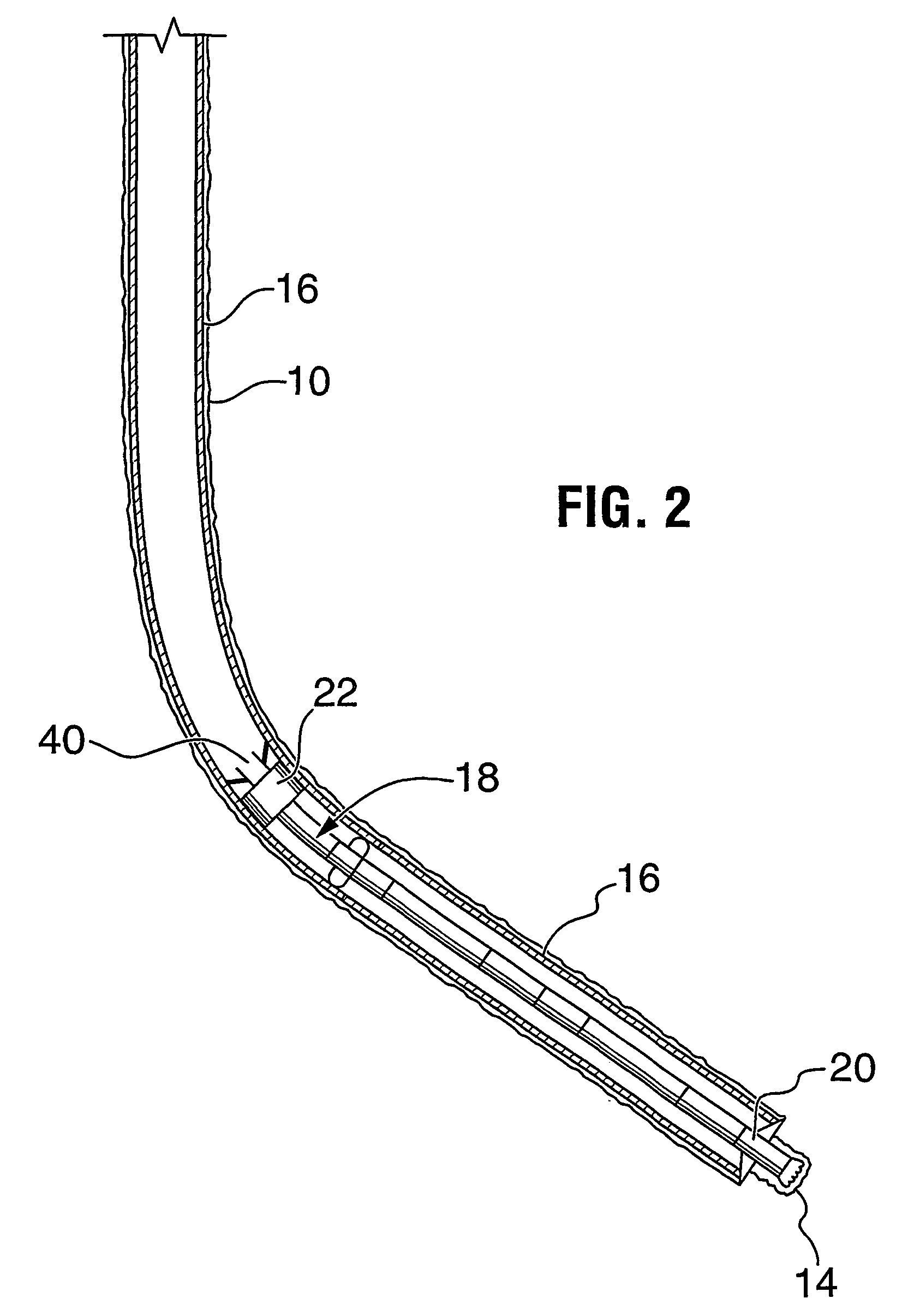
[0019]Referring to FIG. 1, a wellbore 10 is shown during a drilling operation. Wellbore 10 extends between surface 12 and bottom 14 of the wellbore. A drill string 16 formed of casing extends from surface into the wellbore. A drilling assembly 18 is connected at the distal end 16′ of the drill string and extends a distance d from distal end 16′ to total depth 14. Drilling assembly 18 includes a pilot bit 19 and a plurality of underreamers 20. Also included in drilling assembly are a drill lock member 22 for engaging the drilling assembly to the drill string, a drill collar 24, a stabilizer 25, a non-magnetic drill collar 26 including an MWD survey instrument and mud pulse generator 27 and a mud motor 28 for driving the bits 19 and 20. In such an arrangement the distance d is about 100 to 120 feet. This distance can be reduced in a non-directional drilling operation and / or by use of a non-magnetic MWD.

[0020]Drilling assembly 18 is connected into drill string 16 by means of latches on...


PUM


Abstract

A method for drilling boreholes using casing (16) as the drill string and for advancing a casing string toward the bottom of the borehole is described. In the method, the drilling assembly (26) is used as a guide over which the drill string (16) is advanced toward the bottom of the borehole prior to removing the drilling assembly from the wellbore.

Description

FIELD OF THE INVENTION[0001]This invention relates to a method for wellbore drilling and, in particular, a method for drilling a wellbore using casing as the drill string.BACKGROUND OF THE INVENTION[0002]The drilling of wells, for example, for oil and gas production conventionally employs relatively small diameter strings of drill pipe to which is secured a drill bit of somewhat larger diameter. After a selected portion of the wellbore has been drilled, the well bore is usually lined with a string of tubulars known as casing. The casing (herein used to encompass any wellbore liner) has a smaller diameter than the drill bit. This conventional system which requires sequentially drilling the borehole using drill pipe with a drill bit attached thereto, pulling the drill pipe out of the borehole and running casing into the borehole is time consuming and costly. In addition, control of the well is difficult during the period that the drill pipe is being removed and the casing is being run...

Claims


Application Information

Patent Timeline
Patent Type & Authority Patents(United States)
IPC IPC(8): E21B7/04E21B7/20E21B10/66E21B23/08
CPCE21B7/208E21B23/08E21B10/66
Inventor ANGMAN, PER G.
Owner SCHLUMBERGER TECH CORP
Why Eureka
Try Eureka