
High-strength/high-toughness alloy steel drill bit blank

a high-strength, alloy steel technology, applied in the field of steel blanks, can solve the problems of low degree of strength exhibited by conventional steel blanks, lack of material strength necessary for application with today's high-performance drill bits, etc., and achieve the effect of improving strength

Inactive Publication Date: 2006-05-16
SMITH INT INC
View PDF15 Cites 95 Cited by
  • Summary
  • Abstract
  • Description
  • Claims
  • Application Information

AI Technical Summary

Benefits of technology

[0010]Drill bit reinforcing members of this invention made from such steels provide a marked improvement in strength over reinforcing members formed from conventional plain-carbon steels, making them particularly well suited for use in today's high performance drill bit applications

Problems solved by technology

A problem, however, that is known when using such plain-carbon steels for forming the drill bit blanks is that such materials lack a degree of strength necessary for application with today's high performance drill bits.
The low degree of strength exhibited by such conventional steel blanks is caused both by the absence of alloying elements, and by excessive softening that occurs during thermal processes that must be performed during the bit manufacturing process.

Method used


Image

  • High-strength/high-toughness alloy steel drill bit blank
  • High-strength/high-toughness alloy steel drill bit blank
  • High-strength/high-toughness alloy steel drill bit blank

Examples


example no.1

EXAMPLE NO. 1

Low Carbon, Low Alloy Steel Composition

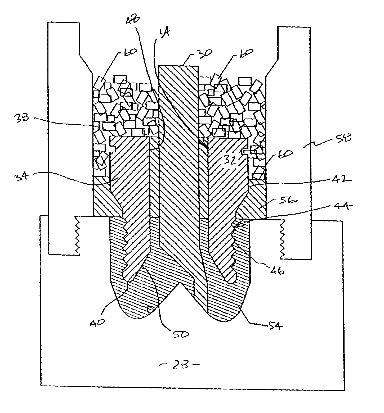
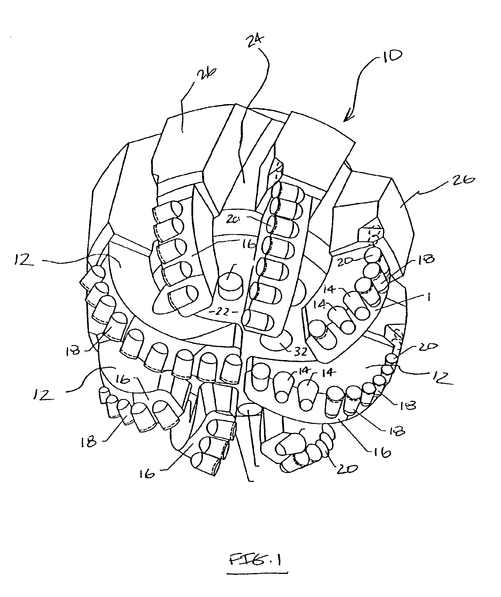
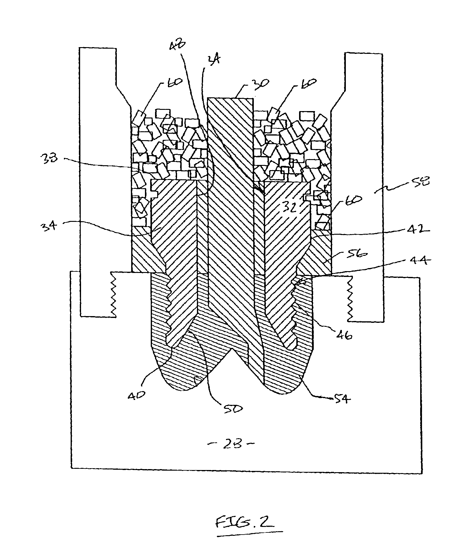
[0040]A PDC drill bit was constructed, according to the principles of this invention, by the above-described infiltration method (illustrated in FIG. 2) comprising lowering a drill bit blank into a graphite mold. The drill bit blank was configured in the manner described above and illustrated in FIGS. 2 and 3, and was formed from a low carbon, low alloy steel comprising carbon in the range of 0.13 to 0.18 pbwt, manganese in the range of 0.7 to 0.9 pbwt, chromium in the range of 0.45 to 0.65 pbwt, nickel in the range of 0.7 to 1 pbwt, molybdenum in the range of 0.45 to 0.65 pbwt as major alloying elements, and a remaining amount iron. Low carbon, low alloy steels comprising this material composition include SAE 4715 steel (also referred to as PS-30) and PS-55 steel. A preferred low carbon, low alloy steels is SAE 4715 steel, which comprises nominally 0.15 pbwt carbon, 0.8 pbwt manganese, 0.55 pbwt chromium, 0.85 pbwt nickel, and 0.5...

example no.2

EXAMPLE NO. 2

Low Carbon, Microalloyed Steel Composition

[0042]A PDC drill bit was constructed, according to the principles of this invention, by the above-described infiltration method (illustrated in FIG. 2) comprising lowering a drill bit blank into a graphite mold. The drill bit blank was configured in the manner described above and illustrated in FIGS. 2 and 3, and was formed from a low carbon, microalloyed steel comprising carbon in the range of from about 0.1 to 0.3 pbwt, manganese in the range of from about 0.9 to 1.5 pbwt, chromium in the range of from about 0.01 to 0.25 pbwt, nickel in the range of from about 0.01 to 0.2 pbwt, molybdenum in the range of from about 0.001 to 0.1 pbwt as major alloying elements, silicon in the range of from about 0.15 to 0.3, one of the microalloying elements in the following ranges: vanadium in the range of from about 0.05 to 0.15 pbwt, niobium in the range of from about 0.01 to 0.1 pbwt, and titanium in the range of from about 0.01 to 1 pbwt,...


PUM

PropertyMeasurementUnit
toughnessaaaaaaaaaa
tensile strengthaaaaaaaaaa
temperatureaaaaaaaaaa

Abstract

Drill bit reinforcing members or blanks of this invention are formed from high-strength steels having a carbon content less than about 0.3 percent by weight, a yield strength of at least 55,000 psi, a tensile strength of at least 80,000 psi, a toughness of at least 40 CVN-L, Ft-lb, and a rate of expansion percentage change less than about 0.0025% / ° F. during austenitic to ferritic phase transformation. In one embodiment, such steel comprises in the range of from about 0.1 to 0.3 percent by weight carbon, 0.5 to 1.5 percent by weight manganese, up to about 0.8 percent by weight chromium, 0.05 to 4 percent by weight nickel, and 0.02 to 0.8 percent by weight molybdenum. In another example, such steel comprises in the range of from about 0.1 to 0.3 percent by weight carbon, 0.9 to 1.5 percent by weight manganese, 0.1 to 0.5 percent by weight silicon, and one or more microalloying element selected from the group consisting of vanadium, niobium, titanium, zirconium, aluminum and mixtures thereof.

Description

FIELD OF THE INVENTION[0001]This invention relates generally to steel blanks used for forming earth-boring drill bits and, more particularly, to steel blanks used for forming polycrystalline diamond compact drill bits having improved properties of strength and toughness when compared to conventional drill bit steel blanks.BACKGROUND OF THE INVENTION[0002]Earth-boring drill bits comprising one or more polycrystalline diamond compact (“PDC”) cutters are known in the art, and are referred to in the industry as PDC bits. Typically, PDC bits include an integral bit body that can be made of steel or fabricated of a hard matrix material such as tungsten carbide (WC). Tungsten carbide or other hard metal matrix body bits have the advantage of higher wear and erosion resistance when compared to steel body bits. Such matrix bits are generally formed by packing a graphite mold with tungsten carbide powder, and then infiltrating the powder with a molten copper-based alloy binder.[0003]A plurali...

Claims


Application Information

Patent Timeline
Patent Type & Authority Patents(United States)
IPC IPC(8): E21B10/00E21B10/42
CPCC22C38/02C22C38/04C22C38/44E21B10/42C22C38/48C22C38/50E21B10/00C22C38/46E21B10/55
Inventor KEMBAIYAN, KUMAR T.OLDHAM, THOMAS W.ZHANG, JOHN YOUHE
Owner SMITH INT INC
Learn More