
Heating systems

a heating system and ceramic heater technology, applied in the field of heating systems, can solve the problems of increased and substantial deformation of the mounting face of heaters over time, and achieve the effect of increasing production cost of ceramic heaters and high production costs

Active Publication Date: 2006-05-16
NGK INSULATORS LTD
View PDF12 Cites 23 Cited by
  • Summary
  • Abstract
  • Description
  • Claims
  • Application Information

AI Technical Summary

Benefits of technology

[0009]However, a production cost for a ceramic heater is high. In particular, a ceramic heater is supported with a tubular supporting member, which is then fixed onto a chamber. A thicker substrate is needed for the heater for providing a strength required for supporting the heater, so that a production cost for the ceramic heater is increased.
[0011]An object of the present invention is to provide a novel heating system for mounting and heating an object, to reduce the thermal deformation of its mounting face over time upon heating, and thus to maintain the flatness of the object.
[0012]Another object of the present invention is to reduce the production cost of the heating system while preserving a mechanical strength required for supporting the system.
[0017]According to the heating system of the present invention, a mounting face for an object is provided in a ceramic substrate to generate heat from the mounting face to heat the object. It is thus possible to reduce the thermal deformation of the mounting face over time upon heating of the ceramic substrate. The flatness of the object may be thus maintained at a low value. Moreover, a plate-shaped and metal supporting member for supporting the back face of the ceramic substrate is provided, so that the production cost of the heating system may be reduced and a mechanical strength required for supporting the system may be assured.

Problems solved by technology

However, a production cost for a ceramic heater is high.
A thicker substrate is needed for the heater for providing a strength required for supporting the heater, so that a production cost for the ceramic heater is increased.
However, when a semiconductor wafer is mounted and heated thereon, the mounting face of the heater may be substantially deformed over time.
The flatness of the wafer cannot be thus maintained.

Method used


Image

  • Heating systems
  • Heating systems
  • Heating systems

Examples


examples

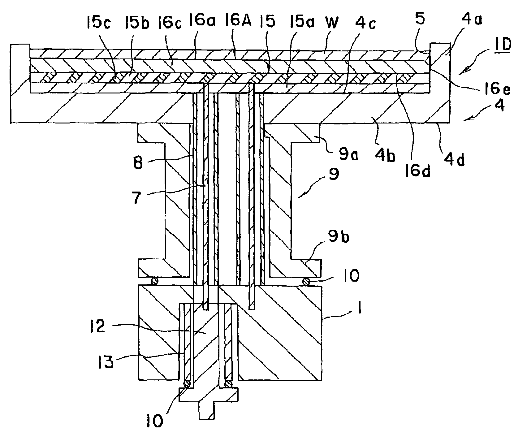
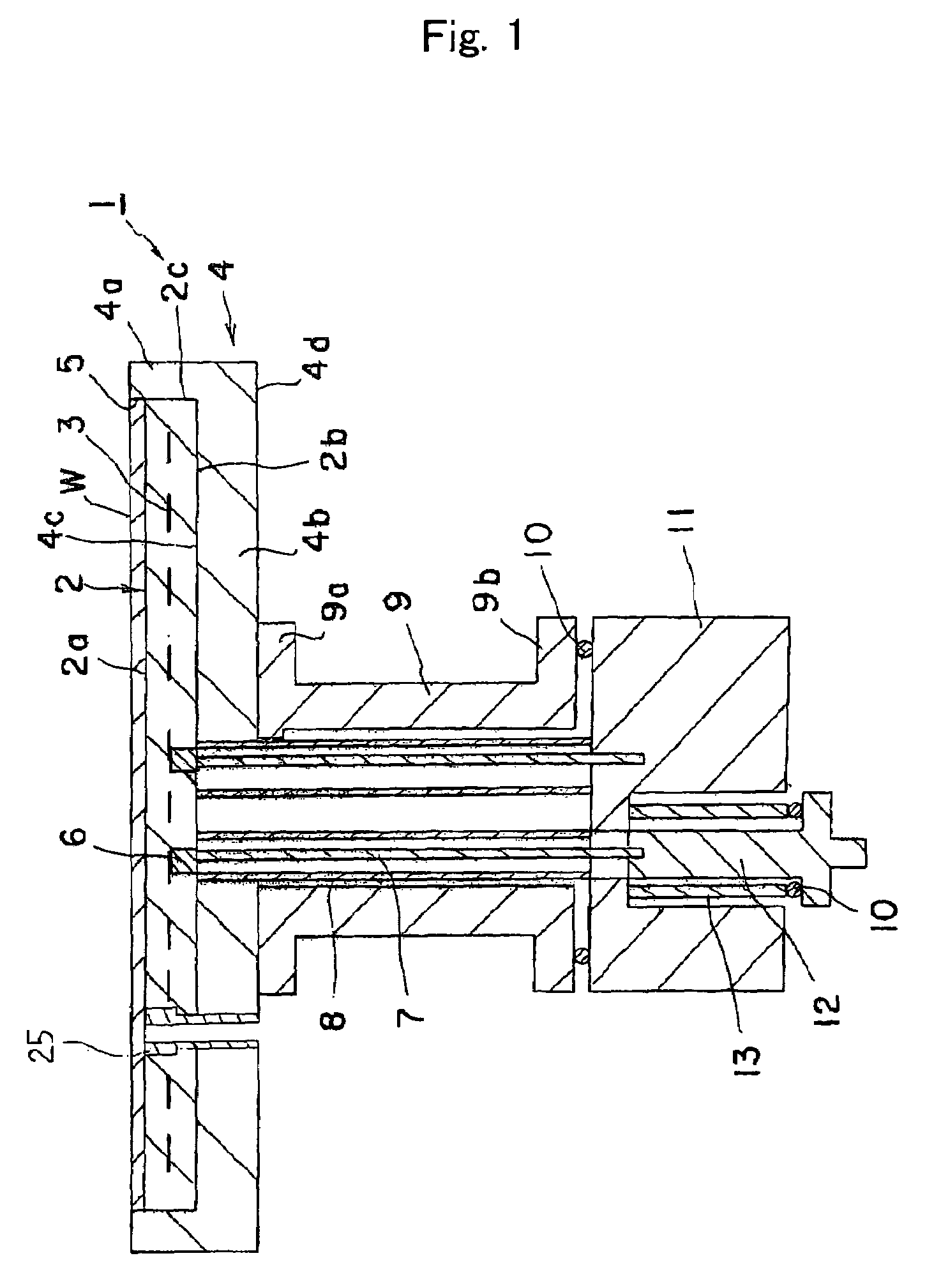
[0054]The heating systems shown in FIGS. 1 and 4 were produced. In the example of FIG. 1, the ceramic substrate 2 was made of aluminum nitride sintered body, in which a molybdenum mesh was embedded as the heat generator. The plate shaped supporting member 4 and supporting member 9 were made of inconel. The ceramic substrate 2 was inserted inside of the plate shaped supporting member 4. The ceramic substrate was made distant from the small protrusions on the inner surface of the supporting member at 50 micrometer. The pins 25 each having a through hole were inserted into the ceramic substrate at 4 positions for avoiding the moving of the substrate (see FIG. 1). A through hole was formed in each pin for functioning as a guide plane for a lift pin used for elevating and descending the object.

[0055]In the example of FIG. 4, the flat plates 15a and 15b were made of mica plates, respectively. A heat generating wire 15c made of SUS was wound around the mica plate 15b. The mica plate 15a wa...


PUM

PropertyMeasurementUnit
Temperatureaaaaaaaaaa
Mechanical strengthaaaaaaaaaa

Abstract

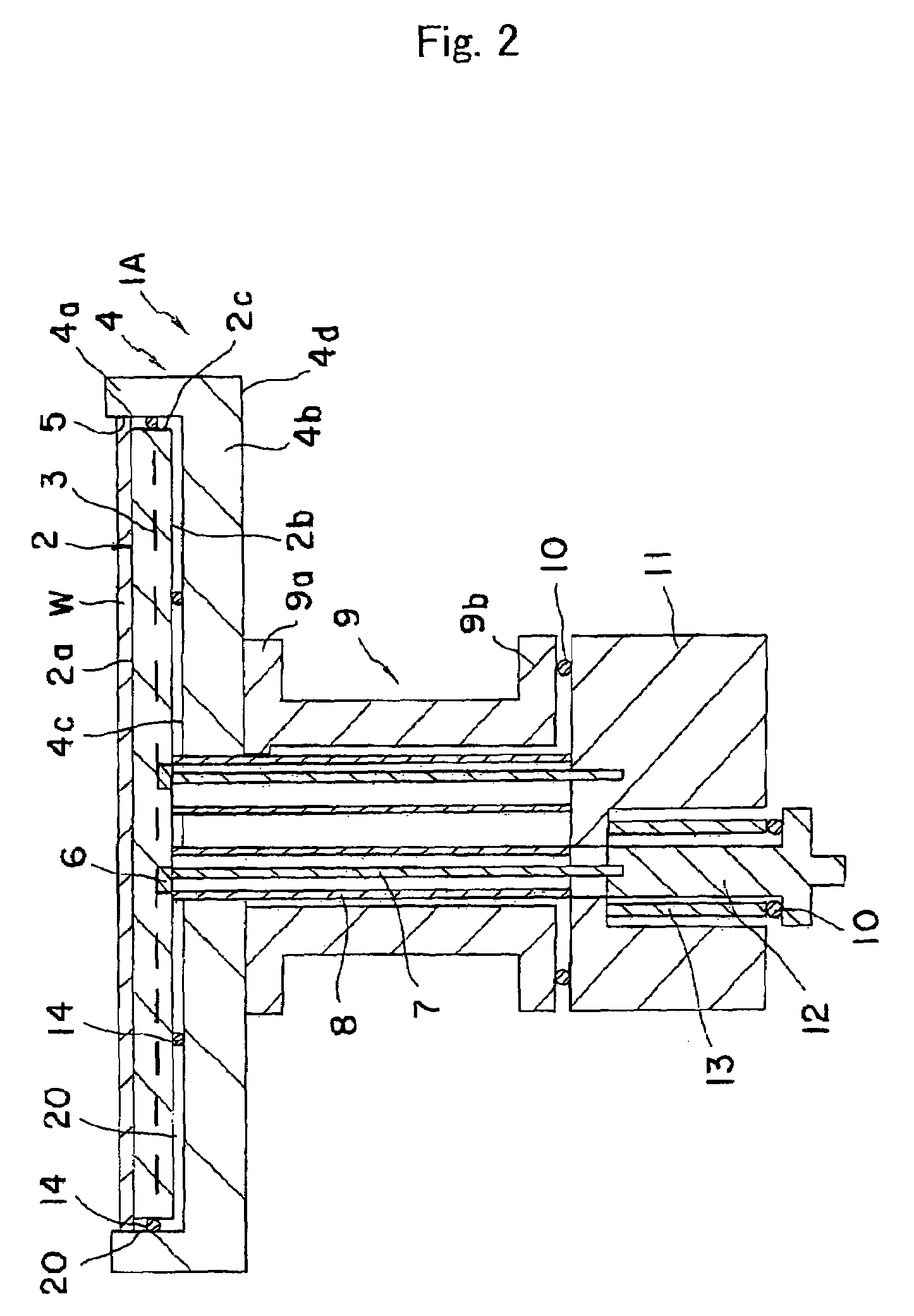
A heating system 1 has a ceramic substrate 2 having a mounting face 2a for mounting an object W, a back face 2b and a side face 2c; a heating means 3 for generating heat from the mounting face 2a of the ceramic substrate 2; and a plate-shaped supporting metal member 4 for supporting the back face 2b of the ceramic substrate 2. According to the system, the thermal deformation of the mounting face upon heating over time may be reduced and the flatness of the object may be maintained at a low value. It is further possible to impart a mechanical strength to the heater sufficient for its handling and to reduce the production cost.

Description

[0001]This application claims the benefit of Japanese Patent Application P2002-333, 950 filed on Nov. 18, 2002, the entirety of which is incorporated by reference.BACKGROUND OF THE INVENTION[0002]1. Field of the Invention[0003]The invention relates to a heating system.[0004]2. Related Art Statement[0005]In a system for producing semiconductors, a ceramic heater may be provided for heating a wafer so as to deposit a semiconductor thin film on the wafer from gaseous raw materials such as silane gas by means of thermal CVD or the like. A so called two-zone heater is known as such ceramic heater. Such two-zone heaters have a ceramic substrate and inner and outer resistance heat generators of a metal having a high melting point embedded within the substrate. Separate power supply terminals are connected to the respective heat generators so that electric power may be applied independently on the respective generators. The inner and outer heat generators may be thus independently controlle...

Claims


Application Information

Patent Timeline
IPC IPC(8): F24H3/00H05B3/74C23C16/458C23C16/46H01L21/00H01L21/205H05B3/06H05B3/10H05B3/18
CPCC23C16/4581H01L21/67103C23C16/46C23C16/4586
Inventor GOTO, YOSHINOBUTSURUTA, HIDEYOSHI
Owner NGK INSULATORS LTD
Learn More