
Power supply circuit with control of rise characteristics of output voltage

a power supply circuit and output voltage technology, applied in the field of power supply circuits, can solve the problem that the charge current ic cannot be set to a lower level if the strategy encounters another problem

Inactive Publication Date: 2006-05-23
DENSO CORP
View PDF24 Cites 30 Cited by
  • Summary
  • Abstract
  • Description
  • Claims
  • Application Information

AI Technical Summary

Benefits of technology

[0012]A second practical object of the present invention is to provide a power supply circuit capable of controlling a rise rate of the output voltage with steadiness, thereby suppressing an overshoot of the output voltage, on condition that the capacitance of a capacitor connected to an output terminal is kept to a lower amount.
[0013]A third practical object of the present invention is to provide a power supply circuit capable of controlling a rise rate of the output voltage with steadiness, thereby avoiding the influence of a ringing phenomenon on the output voltage that is raised.
[0015]In this configuration, the voltage control circuit controls the main transistor such that a detected voltage from the output voltage is consistent with the reference voltage (target voltage), so that the output voltage is made to be equal to the target voltage (i.e., voltage tracking control), except for a startup operation for the power supply. Thus, when the target voltage is constant, the voltage tracking control is carried out as constant-voltage control. Meanwhile, the current limiting circuit controls the main transistor so that the output current does not exceed the limited value. Hence it is possible to prevent the output current to exceed the limited value even when there is an overload (i.e. current limiting control). The current limiting control has priority over the voltage tracking control.
[0017]Accordingly, with reducing the capacitance of a capacitor connected to the output terminal, an overshoot of the output voltage can be suppressed. The capacitor can made compact in size, so that the power supply circuit can be made small and manufacturing cost thereof become low. In a steady sate after a rise of the output voltage, the limited-current-value setting circuit sets the limited amount of the output current to a current amount required by a load connected by the power supply circuit, thus making it sure that the voltage tracking control is carried out normally.
[0019]Preferably, the limited-current-value setting circuit is configured to continuously increase the limited value with an elapse in time during a rise of the output voltage. This makes it possible to increase the output voltage continuously, whereby an overshoot can be suppressed more steadily.
[0021]In this configuration, in particular, the limited-current-value setting circuit increases the limited value of the output current gradually when a ringing component on the applied input voltage is reduced. Hence, in making the output voltage increase in response to an increase in the limed value, voltage fluctuations appearing in the output voltage due to the ringing component of the input voltage can be lowered remarkably. This power supply circuit is able to supply power to a load circuit configured to be reset using the output voltage obtained during its rise operation.

Problems solved by technology

However, because it is impossible to lower the current limit than a supply current to the load (resistor R2) during the operation at a rated voltage output, the charge current Ic cannot be set to a lower level if a larger load current is required.
This strategy encounters another problem.

Method used


Image

  • Power supply circuit with control of rise characteristics of output voltage
  • Power supply circuit with control of rise characteristics of output voltage
  • Power supply circuit with control of rise characteristics of output voltage

Examples


first embodiment

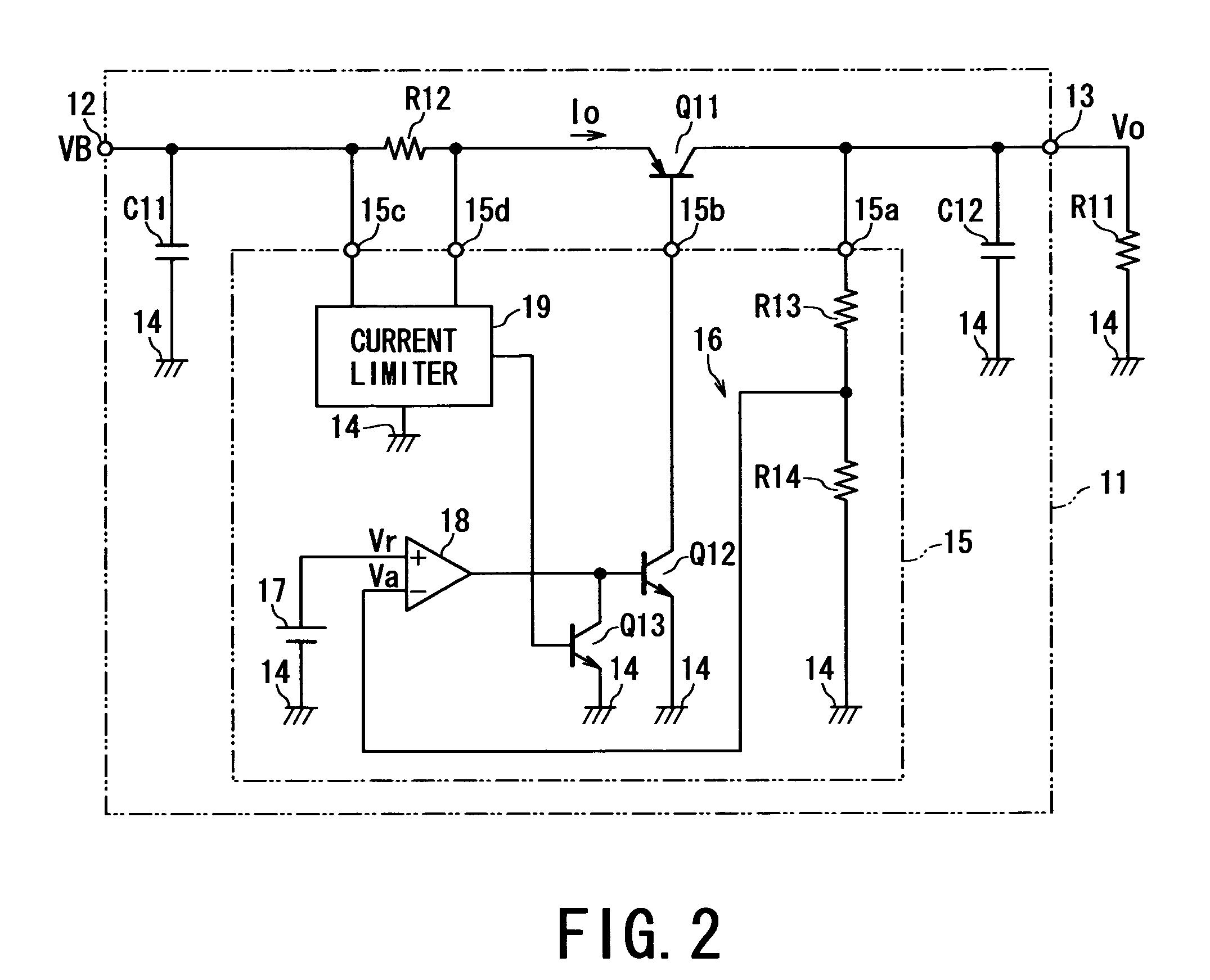
[0044]Referring to FIGS. 2 to 6, the present invention will now be described.

[0045](First Embodiment)

[0046]FIG. 2 shows, partly in block form, the electrical circuitry of a series-regulator type of power supply circuit 11 according to a first embodiment of the present invention. This power supply circuit 11, which is used by, for example, a power supply apparatus mounted to an ECU (Electrical Control Unit) for use in vehicles, is configured to have one substrate on which the entire circuitry is mounted.

[0047]The power supply circuit 11 has not only an input terminal 12 to which a battery voltage VB (for instance, 14 volts) is supplied from an on-vehicle battery (not shown in FIG. 2) but also an output terminal 13 from which an output voltage Vo (for instance, 5 volts) is provided to loads including control IC incorporates into other circuits. Such loads are mounted on the same substrate as that for the power supply circuit 11 and representatively shown by a resistor R11 in FIG. 2.

[0...

second embodiment

[0083](Second Embodiment)

[0084]Referring to FIG. 7, a second embodiment of the present invention will now be described.

[0085]FIG. 7 shows, partly into a block form, the circuitry of a chopper type of switching power supply circuit 35 according to the second embodiment. This power supply circuit 35 steps down an inputted battery voltage VB to output a target voltage of 5 V. In FIG. 7, for the sake of a simplified explanation, the identical or similar components to those of the power supply 11 in FIG. 2 are assigned to the same references as those in FIG. 2.

[0086]As shown in Fig, 7, a reactor L11 is electrically connected between the collector of the transistor Q11 and the output terminal 13, while a Zener diode D16 is electrically connected between the collector of the transistor Q11 and the ground line 14 for protection from an excessive voltage and current flywheel. The polarities of the Zener diode D16 is oriented in the circuitry as it is shown in FIG. 7. The power supply circuit...

third embodiment

[0095](Third Embodiment)

[0096]Referring to FIGS. 8 to 11, a third embodiment of the present invention will now be described.

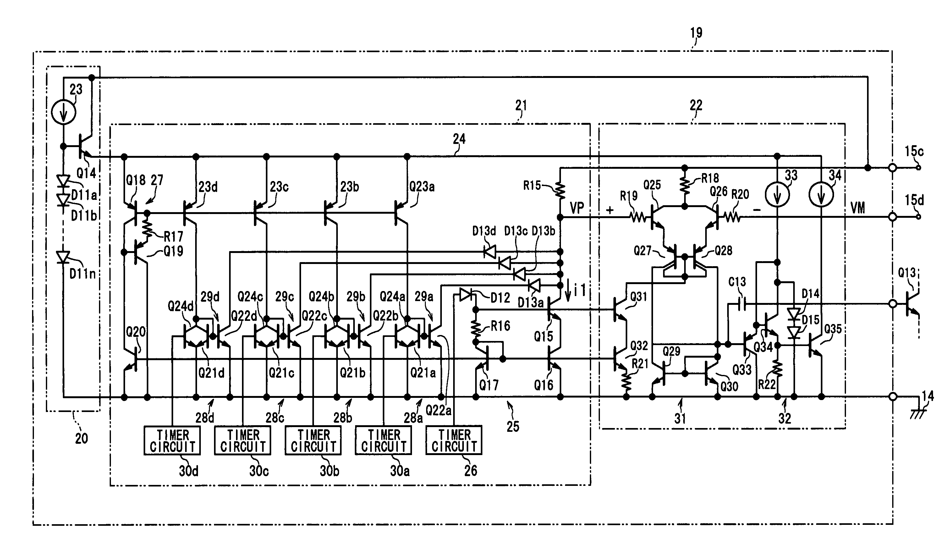
[0097]FIG. 8 details the configuration of electrical circuitry of a series-regulator-type of power supply circuit, which is incorporated in an ECU 100 for use in an automobile engine.

[0098]The ECU 100 has an input terminal 101a, to which a positive polarity terminal of a battery 102 is connected via an ignition switch 103. The ECU 100 has further terminals 101c and 101b, to which the positive and a negative polarity terminals of the battery 102 are connected, respectively. In the following description, a battery voltage given to one input terminal 101a is denoted as VB and a further battery voltage given to the other input terminal 101c is denoted as VBATT.

[0099]The ECU 100 has a variety of circuit blocks, which are illustrated in FIG. 9. In the ECU 100, as shown therein, there are circuit blocks drawn by bold solid lines, that is, a power supply circuit 104, b...


PUM


Abstract

In a power supply circuit, a main transistor, which transmits power from an input terminal to an output terminal, is controlled so that a detected voltage from an input voltage is consistent with a reference voltage indicating a target voltage. An output current is detected and a limited value of the output current is set so that the limited value increases gradually when the output voltage rises up to the target voltage. The main transistor is controlled so that the output current keeps a value less than or equal to the limited value. This configuration is able to suppress an overshoot of the output voltage, thanks to a gradually raised control of the limited value. Additionally, to avoid the influence of a ringing component of the input voltage, a delay control circuit to give a delay to the start of rise of the output voltage can be provided.

Description

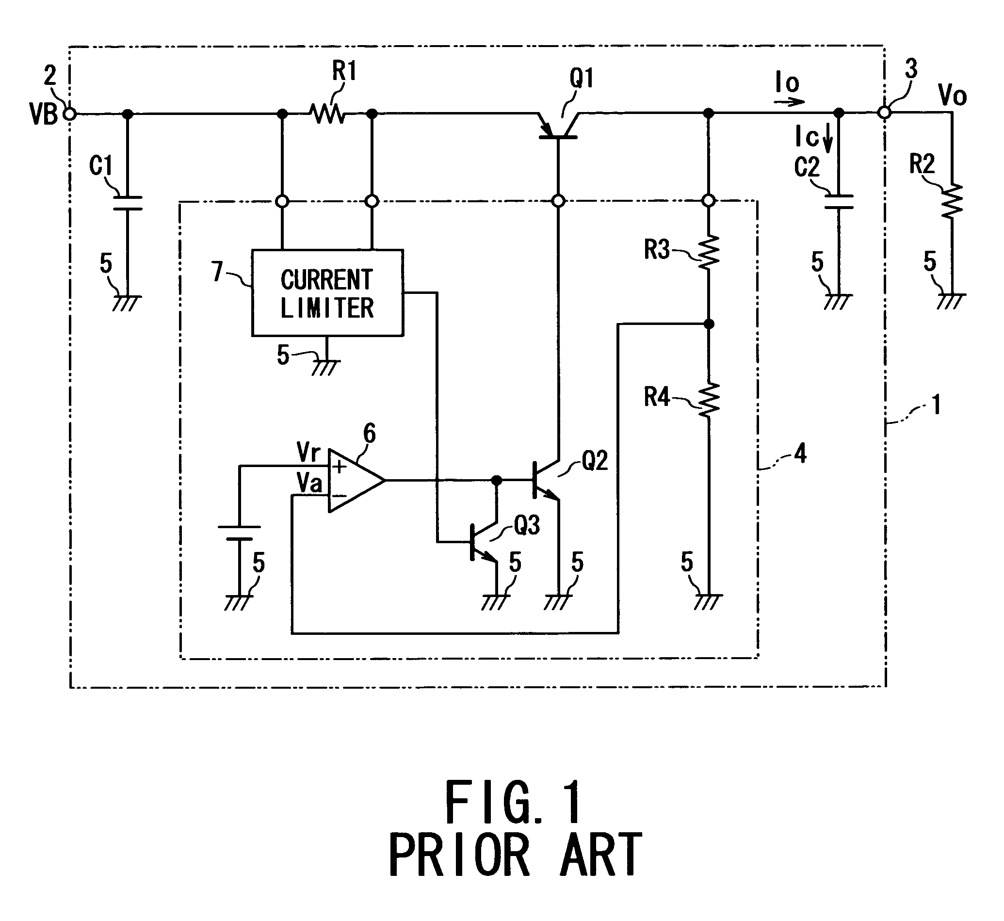
BACKGROUND OF THE INVENTION[0001]1. The Field of the Invention[0002]The present invention relates to a power supply circuit capable of actively controlling rise characteristics of an output voltage to be supplied to an electrical load connected to the power supply circuit.[0003]2. Related Art[0004]Power supply circuits, which are required by almost all electronic apparatuses, can be categorized into many types, one of which is a series-regulator type of power supply circuit.[0005]FIG. 1 exemplifies the electronic configuration of such a series-regulator type of power supply circuit 1, which has been used conventionally. This power supply circuit 1 has an input terminal 2 and an output terminal 3, between which a resistor R1 and a transistor Q1 are inserted in series. The transistor Q1 is placed to be controlled by an IC 4. A capacitor C1 is arranged between the input terminal 2 and a ground line 5 for smoothing input voltage, while another capacitor C2 for smoothing output voltage a...

Claims


Application Information

Patent Timeline
IPC IPC(8): H03K17/56G05F1/10G05F1/56G05F1/575
CPCG05F1/575
Inventor OSAMURA, NOBUYOSHIHUTAMURA, TAKAHARUBAN, HIROYUKI
Owner DENSO CORP
Learn More