Remote temperature measuring system for hostile industrial environments using microwave radiometry

a technology of microwave radiometry and industrial environment, applied in the field of microwave radiometry, can solve the problems of inability or undesirable direct physical contact, mechanical difficulty in maintaining contact for a long time, and inability to direct physical conta

Active Publication Date: 2006-05-30
BOARD OF RGT THE UNIV OF TEXAS SYST +1
View PDF18 Cites 22 Cited by
  • Summary
  • Abstract
  • Description
  • Claims
  • Application Information

AI Technical Summary

Problems solved by technology

However, in many situations direct physical contact is either impossible or undesirable.
Examples include the processing of paper or plastic sheets where contact will damage the material, processing of caustic or extremely high-temperature materials such as cement where contact with the material will eventually damage the instrument, and the processing of any material on a moving conveyor belt where contact is mechanically difficult to maintain for the time required for a measurement.
While such infrared and visible-light remote-temperature measurement devices work well in many applications, there remain a number of industrial circumstances in which these instruments will not work.
(2) The material is being heated with microwave or RF power, often inside a shielded enclosure, and the resulting electromagnetic fields and requisite metallic shielding interfere with the proper operation of the sensor.
Because of these and other shortcomings, remote temperature sensing in industrial applications using infrared or visible-light technology cannot be used in a number of situations that could benefit from it.
However, until solid-state devices such as the gallium-arsenide MESFET were recently developed, microwave radiometers were expensive, bulky systems.
It appears that because of the expense and inconvenience of the equipment used in these experiments, none of the reported radiometers have become available commercially, although some microwave radiometers have been used in laboratory settings for medical purposes.
The “total-power” type of radiometer is insufficiently stable for industrial use, and the other two types are typically too complex for industrial use.

Method used


Image

  • Remote temperature measuring system for hostile industrial environments using microwave radiometry
  • Remote temperature measuring system for hostile industrial environments using microwave radiometry
  • Remote temperature measuring system for hostile industrial environments using microwave radiometry

Examples


first embodiment

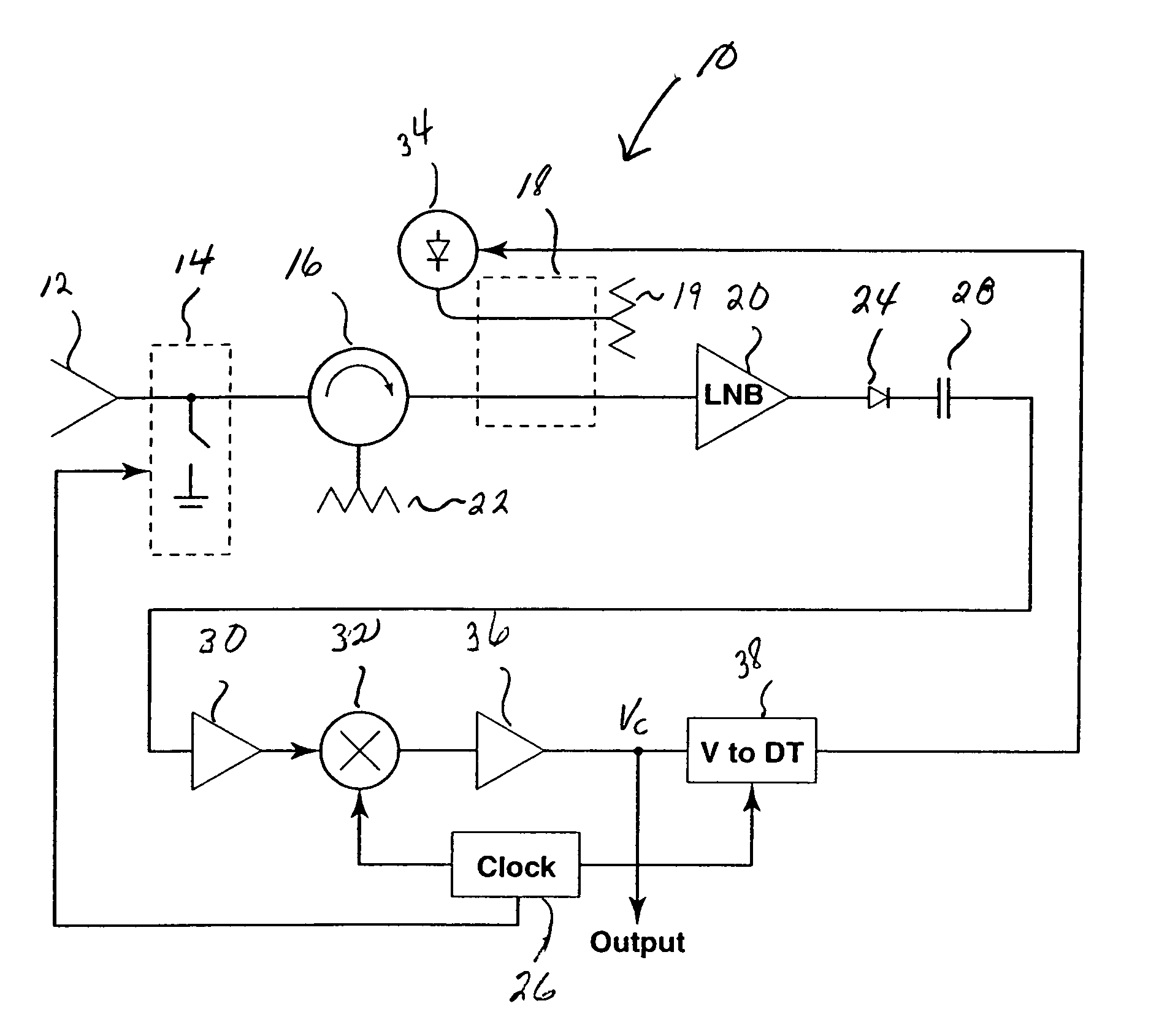
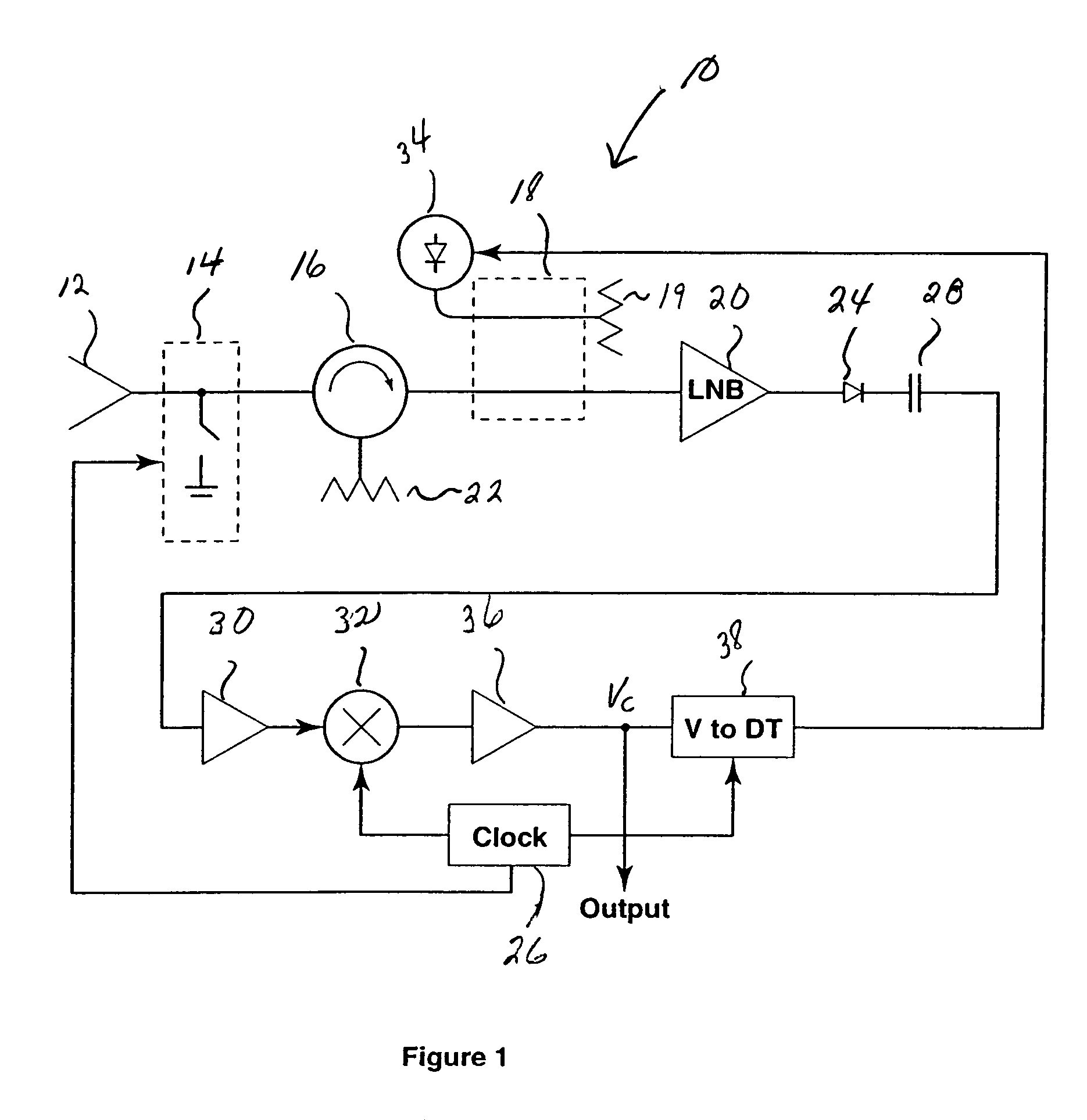
[0028]A first embodiment 10 of remote temperature measuring system using microwave radiometry (or microwave radiometer) of the present invention is shown in FIG. 1. A low-loss antenna 12 (such as a waveguide horn or other waveguide antenna) receives the microwave power radiated in a bandwidth B (Hz) from the object (not shown) whose temperature is to be measured. In the present embodiment, the bandwidth extends from approximately 12 GHz to approximately 13 GHz, but other microwave frequencies and bandwidths can be used. A low-loss single pole-single throw microwave switch 14 alternately allows the incoming microwave energy from the antenna 12 to pass on to the rest of the system, (the PASS mode) or blocks it and becomes a highly reflective circuit element (the BLOCK mode). In the PASS mode, the switch 14 permits the incoming energy to pass through the circulator 16, through the main arm of a directional coupler 18 into an LNB 20. In the, first embodiment, the microwave switch 14 is ...

second embodiment

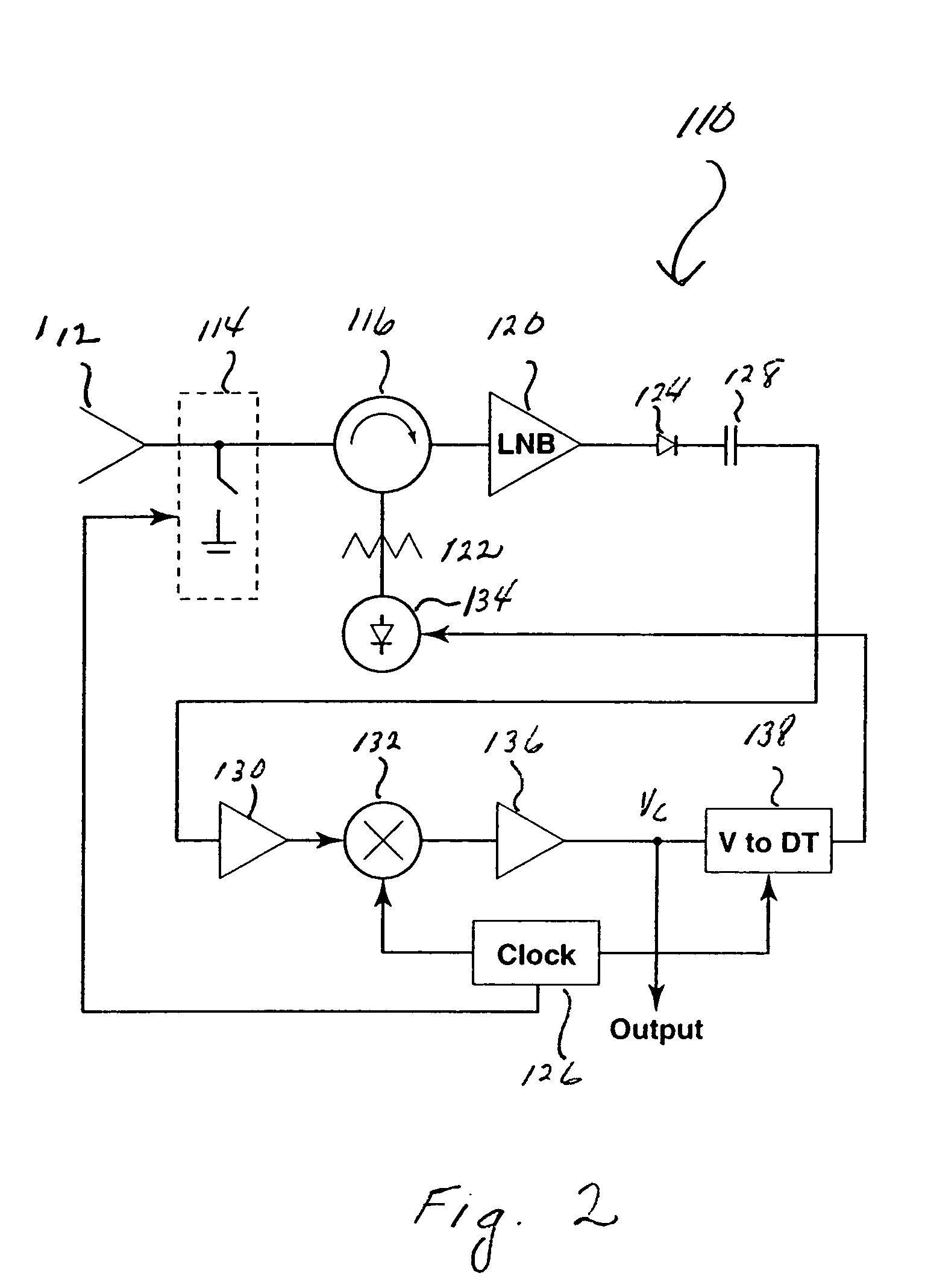
[0057]A system 110 reflecting a second embodiment 110 of the present invention is shown in FIG. 2. In system 110, a low loss antenna 112 receives the microwave power from the object (not shown) whose temperature is to be measured. A low-loss microwave switch 114 alternately allows the incoming microwave energy to pass on to the rest of the system 110 (the PASS mode) or blocks it and becomes a highly reflective circuit element (the BLOCK mode). In the PASS mode, the switch 114 permits the incoming microwave energy to pass through the circulator 116 into the LNB 120. In the PASS mode, LNB 120 filters and amplifies the incoming power, converts it to a lower frequency and outputs the amplified and downconverted power to an internal IF amplifier. The amplified power output of the LNB is then detected by a microwave detector 124.

[0058]In the BLOCK mode, the switch 114 blocks the incoming power from the microwave source and reflects power from both an ambient load 122 and a noise-injection...

third embodiment

Operation of Third Embodiment During Electromagnetic Heating Processes

[0073]Because the typical microwave power sources used for electromagnetic heating emit copious amounts of harmonics, it is not generally possible to employ microwave radiometry to estimate the temperature of objects while they are being subjected to microwave heating. For example, the noise power emitted from a typical 1-KW microwave magnetron operating at a fundamental frequency of 2.45 GHz is several milliwatts at 12 GHz, which is the frequency range we have found to be useful for microwave radiometry. Such noise power exceeds the thermal noise radiated by heated objects, making the latter impossible to measure. One possible way to avoid this problem is to install a high-power waveguide filter between the microwave power source and the chamber holding the material to be heated. This approach is impractical because a filter with the requisite power-handling capacity and rejection characteristics at the harmonic ...


PUM

PropertyMeasurementUnit
wavelength rangeaaaaaaaaaa
temperatureaaaaaaaaaa
frequencyaaaaaaaaaa

Abstract

A system and method for remotely measuring the temperature of an object using microwave radiometry that may be used in hostile environments. A single pole-single throw reflective PIN diode switch is operable in a PASS mode and a BLOCK mode. In the PASS mode, the switch passes the power received from the object to a low-noise block converter (“LNB”) for amplification. In the BLOCK mode, the switch blocks the object power and reflects the load noise power of an ambient temperature load to the LNB. A detector diode detects the amplified power output during both the BLOCK and PASS mode and the AC signal from the detector is converted to an output signal proportional to the difference in the noise powers detected in the PASS and BLOCK modes. A servo loop uses the output signal to generate a feedback signal to a noise injection diode that causes the diode to inject sufficient power into the LNB to automatically maintain a balance between noise power measured in the PASS mode and the combined noise powers measured in the BLOCK mode. The output signal is then used to compute the temperature of the object.

Description

CROSS-REFERENCE TO RELATED APPLICATION[0001]This application is a continuation-in-part of U.S. provisional patent application Ser. No. 60 / 486,309 filed Jul. 11, 2003, entitled “Remote Temperature Measuring System For Hostile Industrial Environments Using Microwave Radiometry.”FIELD OF INVENTION[0002]The present invention relates in general to the field of microwave radiometry and, more particularly, to a substantially simplified form of a noise-injection type microwave radiometer useful in remotely measuring the temperature of objects in hostile environments.BACKGROUND OF INVENTION[0003]In many industrial processes which involve heating, the temperature of the material or object(s) undergoing processing is critical to the successful and efficient completion of the process. Accordingly, suitable means are often incorporated in industrial processes to measure temperature. Most of these means (including but not limited to thermocouples, resistance-temperature devices, and so on) requir...

Claims


Application Information

Patent Timeline
Patent Type & Authority Patents(United States)
IPC IPC(8): G01J5/00G01K11/00
CPCG01K11/006
Inventor STEPHAN, KARL DAVIDPEARCE, JOHN ANTHONY
Owner BOARD OF RGT THE UNIV OF TEXAS SYST
Why Eureka
Try Eureka