
Switching power supply circuit

a power supply circuit and power supply circuit technology, applied in the direction of electric variable regulation, process and machine control, instruments, etc., can solve the problems of deteriorating the ac to dc power conversion efficiency of the power supply circuit, iron loss and copper loss, and achieving the effect of improving the power conversion efficiency and high power factor

Inactive Publication Date: 2006-05-30
SONY CORP
View PDF2 Cites 30 Cited by
  • Summary
  • Abstract
  • Description
  • Claims
  • Application Information

AI Technical Summary

Benefits of technology

The present invention provides a switching power supply circuit that improves power conversion efficiency while maintaining a high power factor. The circuit includes a rectification smoothing section, a switching section, a switching drive section, and an insulating converter transformer. The circuit also includes a primary side series resonance circuit, a secondary side smoothing capacitor, a dc output voltage generation section, and a constant voltage control section. The circuit achieves improved power conversion efficiency without using a power choke coil and achieves further improvement in power conversion efficiency by eliminating the necessity for a power choke coil. The circuit also suppresses the continuity loss of the secondary side rectification current and reduces the reactive power caused by the circuit.

Problems solved by technology

Further, higher harmonics originating from current of a distorted waveform have the possibility of having a bad influence on the load side, and therefore, a countermeasure for suppressing such distortion in a current waveform is required.
The reactive power produced by the power choke coil PCH in this manner deteriorates the ac to dc power conversion efficiency of the power supply circuit.
If the inductance value of the power choke coil PCH is set to a higher value in order to obtain a sufficient effect of power factor improvement, then such iron loss and copper loss as mentioned above are likely to increase, which gives rise to further deterioration of the power conversion efficiency.

Method used


Image

  • Switching power supply circuit
  • Switching power supply circuit
  • Switching power supply circuit

Examples


first embodiment

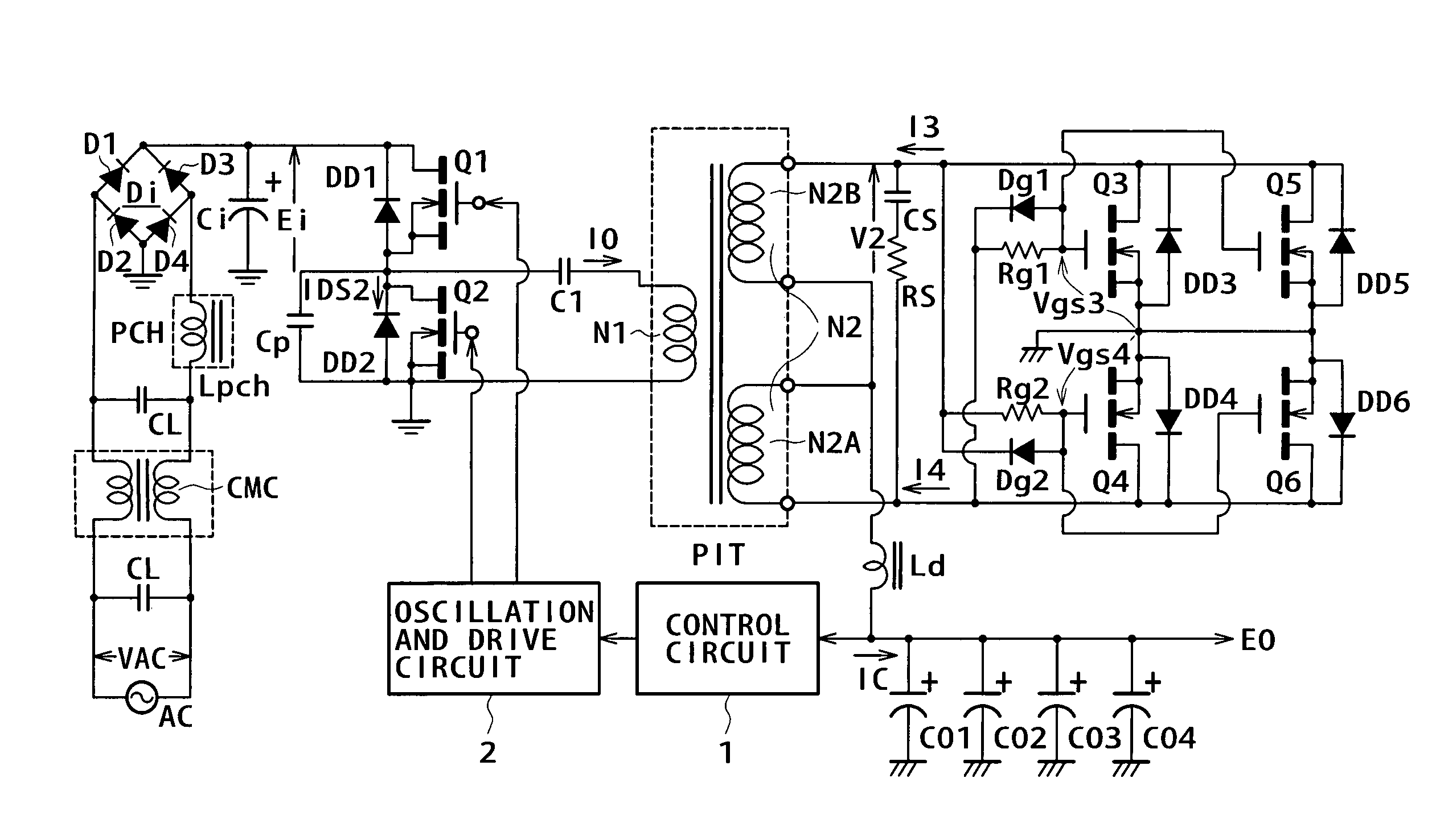
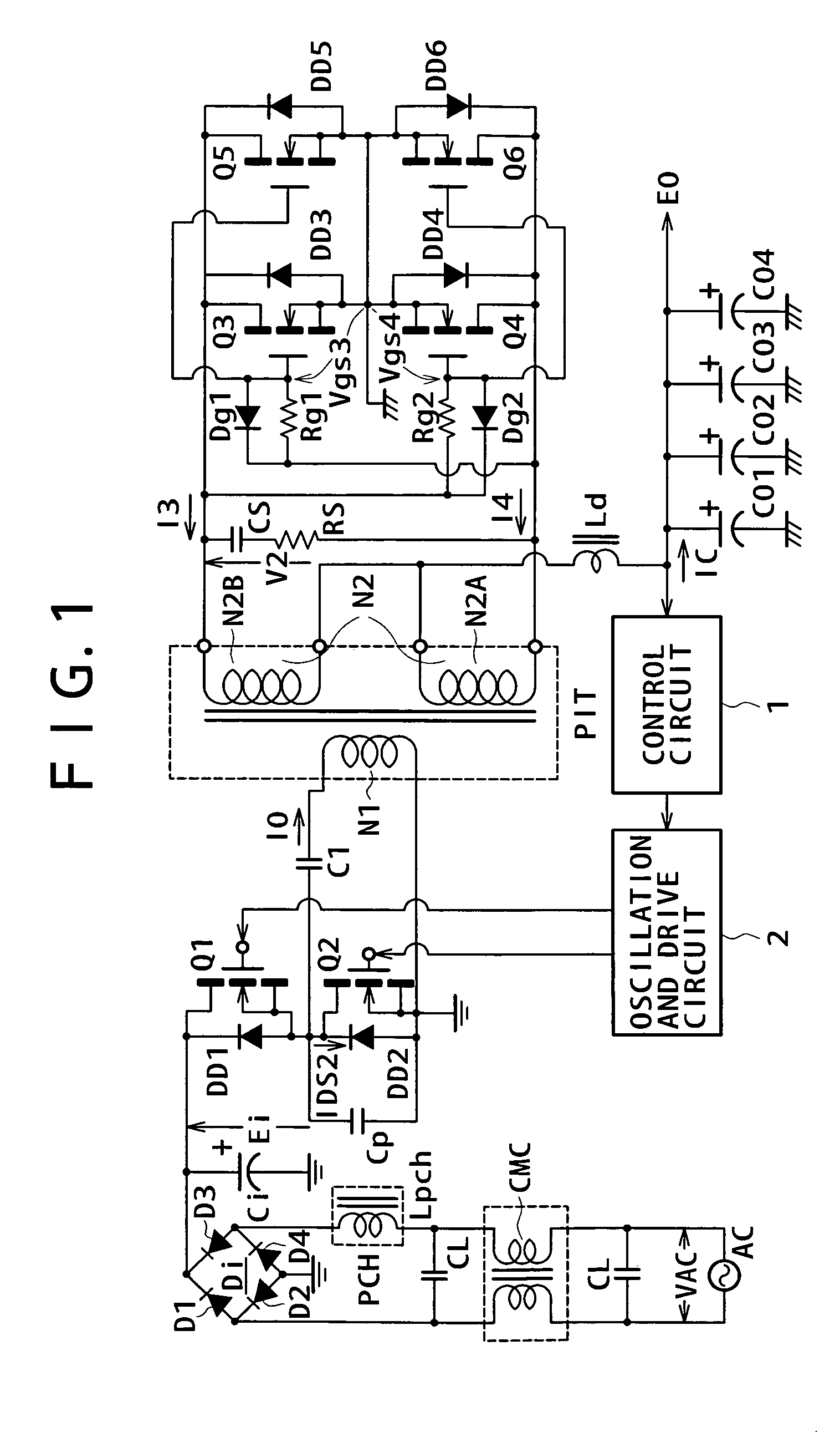
[0066]FIG. 1 shows a basic configuration of a switching power supply circuit to which the present invention can be applied and on which the present invention hereinafter described is based.

[0067]The switching power supply circuit shown in FIG. 1 basically adopts the configuration of the switching power supply circuit described hereinabove with reference to FIG. 30 and includes a synchronous rectification circuit formed on the secondary side to attain the improvement of the ac to dc power conversion efficiency.

[0068]Here, a relationship between such a synchronous rectification circuit as just mentioned and the ac to dc power conversion efficiency is described briefly.

[0069]First, it is known that, where a power supply circuit has a configuration wherein the switching frequency of a switching element on the primary side is variably controlled to achieve stabilization of a secondary side dc output voltage, such a phenomenon as described below occurs. In particular, where the switching ...

second embodiment

[0155]FIG. 6 shows another basic configuration of a switching power supply circuit to which the present invention can be applied and on which the present invention hereinafter described is based.

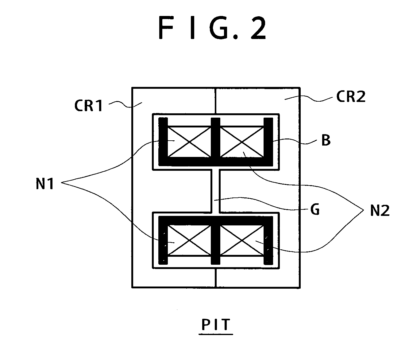
[0156]Also the basic configuration shown in FIG. 6 includes a power choke coil PCH to achieve improvement of the power factor similarly as in the basic configuration shown in FIG. 1 and includes an isolating converter transformer PIT having a similar configuration to that described hereinabove with reference to FIG. 2. The basic configuration shown in FIG. 6 thereby achieves expansion of the continuous mode and reduction of the reactive power on the secondary side to achieve improvement of the power conversion efficiency.

[0157]Further, the configuration shown in FIG. 6 is configured so as to be ready for an AC 100 V system while the configuration of FIG. 1 is configured so as to be ready for a 200 V system of the commercial AC power supply AC.

[0158]As the configuration ready for an AC 100 V ...

third embodiment

[0298]A configuration of a switching power supply circuit according to the present invention is shown in FIG. 18.

[0299]The switching power supply circuit of the third embodiment has the basic configuration ready for an ac 200 V system similarly to the first embodiment described hereinabove with reference to FIG. 9. The switching power supply circuit further includes a power factor improving circuit 5 different from the power factor improving circuit 3 provided in the circuit of FIG. 9 as a power factor improving circuit of the voltage feedback system.

[0300]Accordingly, the power supply circuit shown in FIG. 18 is similar to the circuit of FIG. 9 except the configuration of the power factor improving circuit, and therefore, the following description is given principally of the configuration of the power factor improving circuit 5.

[0301]The power factor improving circuit 5 includes a bridge rectification circuit Di formed from rectification diodes D1, D2, D3, D4 as seen in FIG. 18. Th...


PUM


Abstract

A switching power supply circuit achieves improvement of the power conversion efficiency while a high power factor is maintained, in which the power factor of a current resonance converter is improved by feeding back a switching output to a rectification current path to selectively interrupt the rectification current, thereby to expand the conduction angle of ac input current. This allows elimination of a power choke coil to achieve improvement of the power conversion efficiency. Further, the magnetic flux density of an insulating converter transformer is set lower than a predetermined level, so that secondary side rectification current normally maintains a continuous mode irrespective of a variation of the load or the input voltage. This decreases the power loss that appears when the secondary side rectification current is placed into a discontinuous mode and thereby achieves further improvement of the power conversion efficiency.

Description

BACKGROUND OF THE INVENTION[0001]This invention relates to a switching power supply circuit provided as a power supply in various electronic apparatus.[0002]In recent years, thanks to the development of a switching element which can withstand comparatively high current and voltage of a high frequency, most of power supply circuits which rectify an ac voltage from a commercial power supply to obtain a desired dc voltage are formed as power supply circuits of the switching system.[0003]A switching power supply circuit uses a high switching frequency to decrease the size of a transformer and other parts and is formed as a DC-DC converter of high power for use as a power supply for various electronic apparatus.[0004]Incidentally, it is conventionally known that, if an ac input voltage is rectified, then the current flowing through a smoothing circuit has a distorted waveform, which deteriorates the power factor representative of efficiency in utilization of a power supply.[0005]Further,...

Claims


Application Information

Patent Timeline
Patent Type & Authority Patents(United States)
IPC IPC(8): H02M3/335H02M7/06H02M3/28
CPCH02M1/4258H02M3/33592Y02B70/1491Y02B70/1475H02M2001/0058Y02B70/126Y02B70/10Y02P80/10H02M1/0058H02M3/28
Inventor YASUMURA, MASAYUKI
Owner SONY CORP
Learn More