Return link design for PSD limited mobile satellite communication systems

a technology of mobile satellite communication system and return link, which is applied in the direction of power management, transmission monitoring, wireless commuication services, etc., to achieve the effect of less bandwidth to transmit, more accurate control of the power level of the signal, and quick determination of the power level needed

Inactive Publication Date: 2006-05-30
THE BOEING CO
View PDF41 Cites 49 Cited by
  • Summary
  • Abstract
  • Description
  • Claims
  • Application Information

AI Technical Summary

Benefits of technology

[0024]Every mobile terminal operating within the coverage region sends a request-to-transmit signal to the central controller via the satellite-based transponder. The central controller determines the PSD of each mobile terminal and sums the PSDs together to produce the aggregate PSD. Only if the aggregate PSD is below the regulatory PSD limit does the central controller then authorize a particular mobile terminal to transmit. If the PSD of any subsequent mobile terminal requesting authorization to transmit is determined by the central controller to produce an aggregate PSD that would exceed the predetermined regulatory PSD limit, then the central controller will deny authorization to transmit to the mobile terminal making the request. In this manner a plurality of mobile terminals are allowed to access the satellite-based transponder provided the aggregate PSD of the RF transmissions from each mobile platform do not exceed the predetermined regulatory PSD limit. In this manner, the efficiency of the system is also maximized by operating near the regulatory PSD limit (with appropriate margins for errors in estimating PSD). Making full use of the capacity of expensive satellite transponders is necessary for reducing system operating costs and maximizing profitability.
[0031]In the interval between power control commands, a second control loop is employed by the mobile terminal to maintain the transmit EIRP at the commanded level The second closed control loop is required for stabilizing the transmit EIRP during rapid movement and / or attitude changes of the mobile platform. The second closed control loop thus reduces the power control errors caused by the round trip delay between the ground-based central controller and the mobile terminal, which is approximately 0.5 seconds, round trip.
[0034]In the preferred embodiment of the invention, the return link between the mobile terminal and the ground station is limited in performance by the portion of the link between the aircraft and the satellite. The portion of the return link between the satellite and the ground does not degrade the performance of the return link in the preferred embodiment. In practice this is accomplished by selection of a ground station antenna with sufficiently high gain over noise temperature (G / T). Under these conditions, the receive Eb / No at the ground station is equal to the receive Eb / No at the satellite and the equation for reverse calculating the EIRP of the mobile terminal is substantially simplified making possible the use of this method in practical systems.
[0036]A preferred system for implementing power control over the return link signal from the mobile terminal is also disclosed. This system makes use of a scan angle compensator for determining the compensation signal to be applied to the transmit antenna of the mobile terminal to account for power variations in the signal transmitted by the mobile terminal as the attitude of the mobile platform carrying the mobile terminal changes. A separate control loop incorporating a ground controller and a reporting algorithm is used to examine power variations received at a ground or base station from a satellite-based transponder and to provide power correction commands back to the mobile platform which more precisely control the power level of the signal transmitted by the mobile terminal. The scan angle compensator essentially forms an open loop control circuit which functions in connection with pre-stored information relating to the effects of attitude changes of the mobile platform on the power level of the signal transmitted from the mobile platform's mobile terminal. The scan angle compensator is able to analyze scan angle measurements, or to infer the needed scan angle measurement information from attitude information supplied by, for example, an inertial reference unit (IRU) of the mobile platform, and to quickly determine needed changes in the power level of the signal being transmitted from the mobile terminal to prevent interference with satellites other than the target satellite.
[0037]The ground loop controller portion of the system operates to examine the Eb / No of the signal received by the satellite-based transponder and to determine appropriate power level correction commands that need to be applied to the signal by the mobile terminal to prevent interference with satellites in the vicinity of the target satellite. The ground loop controller transmits power level correction commands to the mobile terminal via the satellite-based transponder which serve to inform the mobile terminal as to the needed degree of power level correction. Advantageously, since the power level correction commands represent merely a value indicating the incremental change that is needed in the power level of the transmitted signal and since they are only transmitted when the ground loop controller determines that a meaningful correction can be applied, these commands require less bandwidth to transmit than would a signal relating to a specific power level that is transmitted at regular intervals regardless of the power level correction it would effect. The scan angle compensator and the ground loop controller thus provide two independent control loops for more accurately controlling the power level of the signal transmitted from the mobile terminal.

Problems solved by technology

Broadband data and video services, on which our society and economy have grown to depend, have heretofore generally not been readily available to users on board mobile platforms such as aircraft, ships, trains, automobiles, etc.
While the technology exists to deliver such services to all forms of mobile platforms, past solutions have been generally quite expensive, low data rate and / or available to only very limited markets of government / military users and some high-end maritime markets (i.e., cruise ships).
Previously developed systems which have attempted to provide live TV and data services to mobile platforms have done so with only limited success.
One major obstacle has been the high cost of access to such broadband data and video services.
Another problem is the limited capacity of previously developed systems, which is insufficient for mobile platforms carrying dozens, or even hundreds, of individuals who each may be simultaneously requesting different channels of programming or different data services.
Furthermore, presently existing systems are generally not readily scalable to address the demands of the traveling public.
However, no system or method presently exists for providing high speed (i.e., greater than 64 Kbps) data networking services to groups of users on mobile or remote platforms, let alone for providing such high-speed networking services together with video services.
These systems are very limited in their link capability (primarily use communication links developed for telephony) and the service is very expensive (greater than about $1.00 per minute for voice connection).
For these reasons, and in view of adherent limitations on the capacity of such systems, such systems have met with limited commercial success and acceptance.
These connection forms have several drawbacks:1) a limited connection bandwidth (typically less than 64 Kbps);2) limited overall system capacity (due to limited frequency spectrum); and3) high expense.
Inmarsat operates in the L-band frequency spectrum, where there is very little bandwidth and capacity available for providing broadband services to the traveling public.
NATS based solutions (i.e., GTE Airfone, AT&T Claircom), familiar to domestic airline travelers who use seat back-mounted telephones, also provide very limited capacity because of operation at L-band.
These systems also suffer from the additional problem that connectivity is only available over land.
Current mobile platform connection methods are inherently narrow band and restrict the flow of data to the point where common networking tasks are impossible.
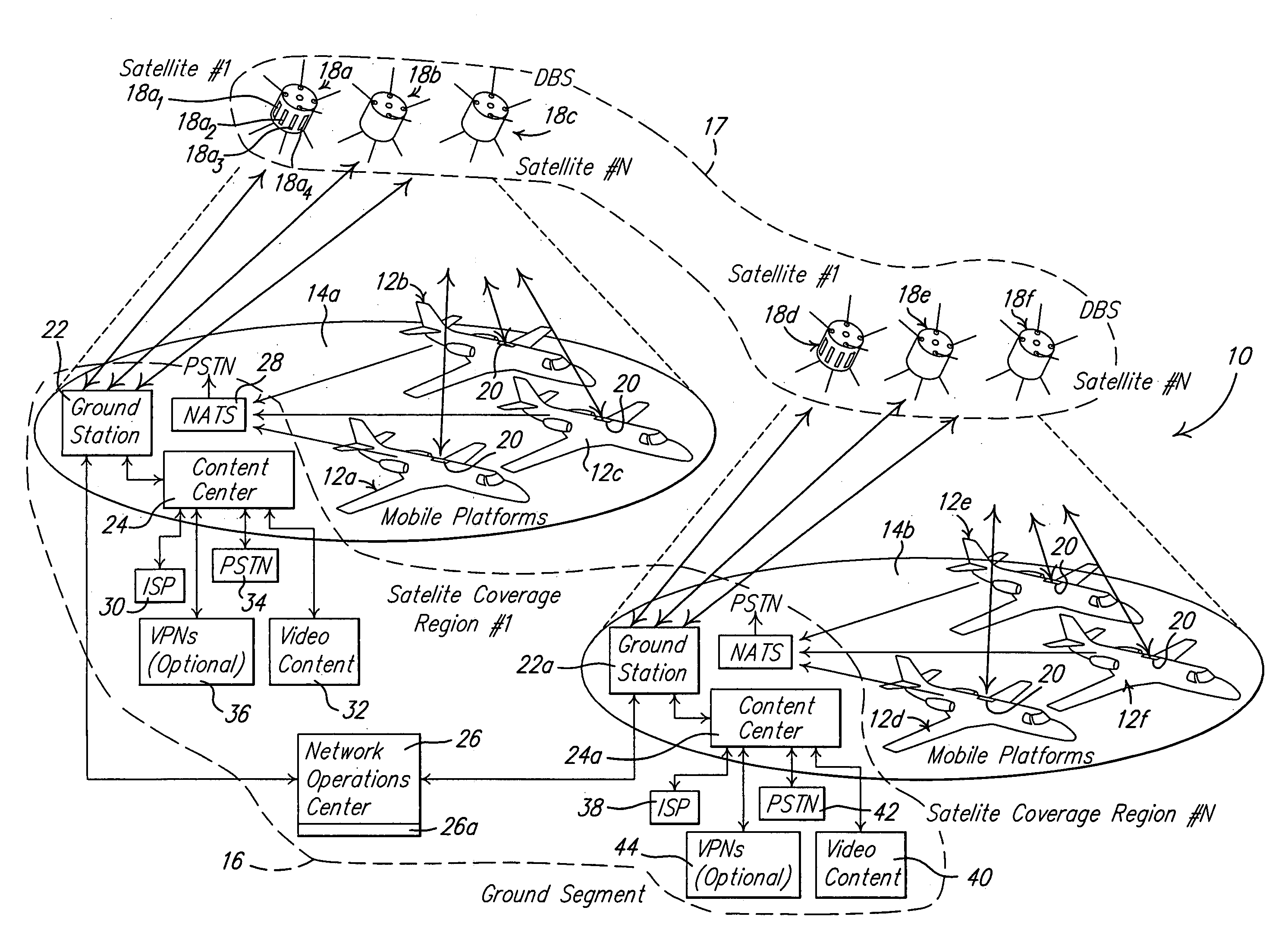
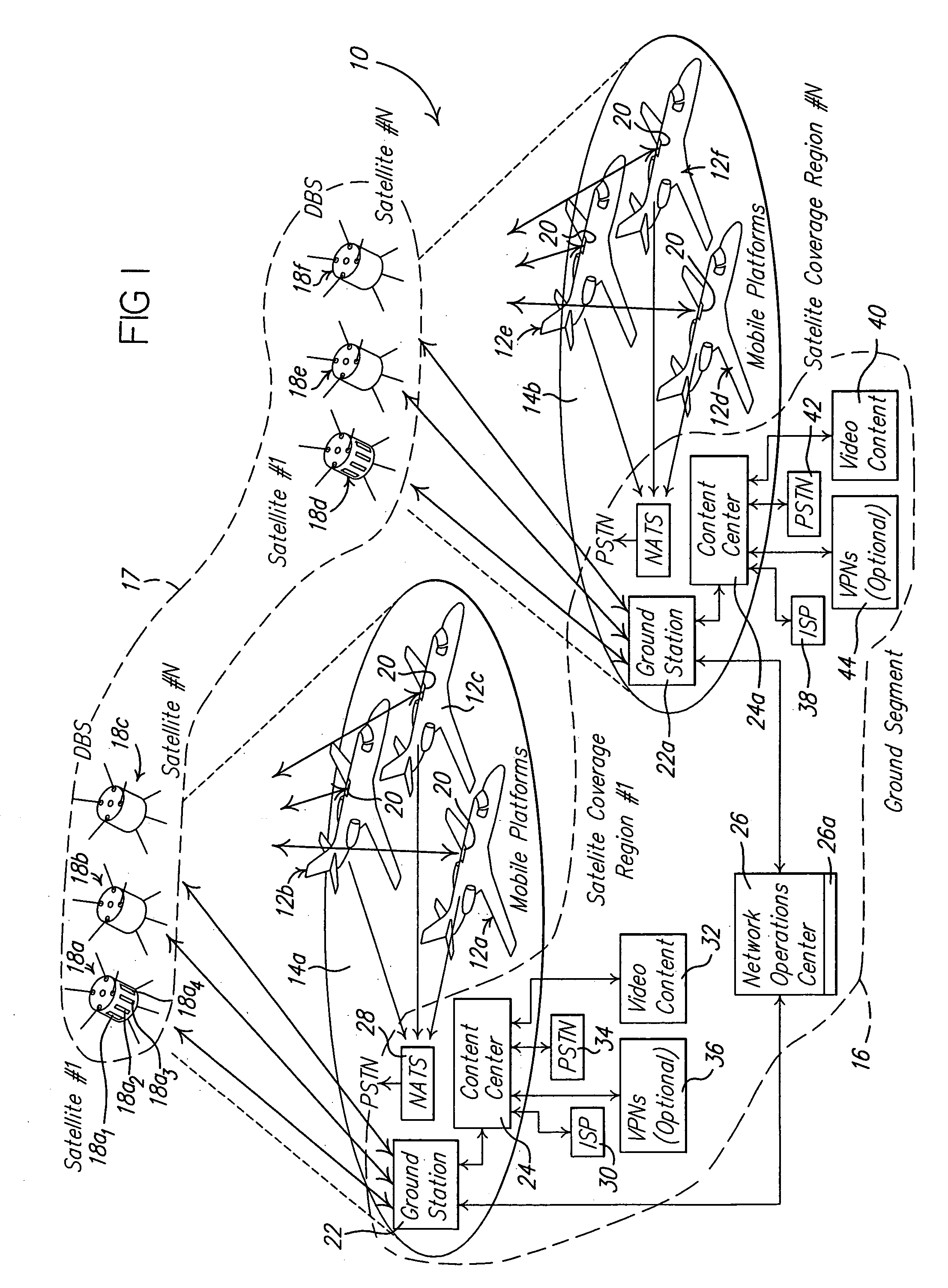
With present day systems which attempt to provide a means by which a plurality of mobile platforms transmit data to a shared satellite-based transponder, a particularly troubling problem has been how to efficiently operate and manage a plurality of small aperture mobile transmitting terminals that are geographically distributed over a wide area, with each mobile terminal transmitting at a different power spectral density (PSD) level according to its specific aperture size, the location of the mobile platform and the data rate at which data is being transmitted.
Also, mobile transmit antennas can interfere with communications on satellites in non-geostationary orbits (NGSOs).
Put differently, such mobile transmit antennas can easily produce signals that interfere with the operation of GSO and NGSO satellites that are adjacent to the target satellite.
When a plurality of mobile platforms are transmitting RF signals to a common transponder within a given coverage region, it becomes very difficult to manage the PSD of individual mobile platforms to ensure that the “aggregate” PSD never exceeds the regulatory limits, while simultaneously attempting to maximize the total number of mobile platforms accessing the transponder.
This method of operation is wasteful of PSD because the unused PSD in each channel cannot be used.
Furthermore, MCPC cannot be adapted to efficient PSD operation because channel management becomes prohibitively complex, especially for applications using mobile terminals.
Similarly, time division multiple access (TDMA) methods have only one terminal accessing a channel or time slot at any time so that the available channel PSD is fixed and usually exceeds the requirements of the channel user.
Therefore, PSD is wasted and cannot be reused.
With these previously developed methods, individual accesses do not usually occur at the maximum allowable PSD, so that there will usually be some amount of PSD that is unused or wasted in every channel.
This is the primary drawback of all previously developed methods.
The above described scenarios where only one terminal is transmitting within a channel or time slot at any given time thus present the classic problem of allocating a fixed size resource (i.e., PSD) to variable sized users.
The fixed size resource must then be sized for the worst case (i.e., maximum PSD) user so there will always be inefficiency with these approaches.
If the variations between users is small, then the inefficiency can be reasonably low, but for any other application where there are large differences in user PSD requirements, the inefficiency becomes substantial.
With this method of operation there are statistical variations in PSD levels and interference between users that would be unacceptable for high-quality satellite data communication systems.

Method used


Image

  • Return link design for PSD limited mobile satellite communication systems
  • Return link design for PSD limited mobile satellite communication systems
  • Return link design for PSD limited mobile satellite communication systems

Examples


Embodiment Construction

[0055]Referring to FIG. 1, there is shown a system 10 in accordance with a preferred embodiment of the present invention for providing data content to and from a plurality of moving platforms 12a–12f in one or more distinct coverage regions 14a and 14b. The system 10 generally comprises a ground segment 16, a plurality of satellites 18a–18f forming a space segment 17, and a mobile system 20 disposed on each moving platform 12. The moving platforms could comprise aircraft, cruise ships or any other moving vehicle. Thus, the illustration of the moving platforms 12 as aircraft in the figures herein and the reference to the mobile platforms as aircraft throughout the following description should be understood as exemplary only, and not be construed as limiting the applicability of the system 10 to only aircraft.

[0056]The space segment 17 may include any number of satellites 18 in each coverage region 14a and 14b needed to provide coverage for each region. Satellites 18a, 18b, 18d and 18...


PUM


Abstract

A system and method for managing access to a satellite-based transponder by a plurality of aircraft each having a mobile radio frequency (RF) system. The system employs a ground-based, central control system for managing access to the satellite-based transponder so that the aggregate power spectral density (PSD) of the RF signals of all the mobile systems does not exceed, at any time, limits established by regulatory agencies to prevent interference between satellite systems. This is accomplished by a dual control loop arrangement for monitoring the signal-to-noise ratio (Eb / No) of the RF signal transmitted by the satellite-based transponder. A ground-based control loop is used whereby a ground-based central controller monitors the Eb / No and transmits commands to the aircraft (via the satellite transponder) to maintain the Eb / No of the transmitted signal within a predetermined range. A fast scan angle compensation is used by the mobile system of the aircraft to implement another control loop to further adjust the transmit power. This control loop maintains the Eb / No of the signal transmitted to the satellite-based transponder at the commanded level inbetween updates from the ground-based central controller.

Description

CROSS REFERENCE TO RELATED APPLICATIONS[0001]This application is a continuation-in-part of U.S. Ser. No. 09 / 728,605, filed Dec. 1, 2000, presently pending, which is a continuation-in-part of U.S. Ser. No. 09 / 672,378, filed Sep. 20, 2000, presently pending.TECHNICAL FIELD[0002]In the interval between power control commands, a second control loop is employed by the mobile terminal to maintain the transmit EIRP at the commanded level. The second closed control loop is required for stabilizing the transmit EIRP during rapid movement and / or attitude changes of the mobile platform. The second closed control loop thus reduces the power control errors caused by the round trip delay between the ground-based central controller and the mobile terminal, which is approximately 0.5 seconds, round trip.BACKGROUND OF THE INVENTION[0003]Broadband data and video services, on which our society and economy have grown to depend, have heretofore generally not been readily available to users on board mobi...

Claims


Application Information

Patent Timeline
Patent Type & Authority Patents(United States)
IPC IPC(8): H04B7/185H04B7/19H04B7/26
CPCH04B7/18506H04B7/18508H04W52/283H04W52/08H04B7/18513
Inventor DE LA CHAPELLE, MICHAELO'BRIEN, KEVIN M.
Owner THE BOEING CO
Why Eureka
Try Eureka