Preappliable phase change thermal interface pad

a technology of thermal interface and phase change, which is applied in the direction of cellulosic plastic layered products, semiconductor/solid-state device details, lighting and heating apparatus, etc., can solve the problems of affecting the operation of the device, affecting the heat transfer effect of the electronic component, and affecting the heat transfer effect of the device, etc., to achieve convenient manufacturing, simple construction, and low cost

Inactive Publication Date: 2006-06-06
HENKEL CORP
View PDF37 Cites 25 Cited by
  • Summary
  • Abstract
  • Description
  • Claims
  • Application Information

AI Technical Summary

Benefits of technology

[0013]Still further object of the present invention are to provide a thermal interface that may be adhesively secured in position relative to heat sink and an electronic component that is of simple co

Problems solved by technology

In this regard such electronic components, the most common being computer chip microprocessors, generate sufficient heat to adversely affect their operation unless adequate heat dissipation is provided.
According to contemporary practice, however, the use of an adhesive material to attach the heat conductive interface to either the electronic component or the heat sink is generally undesirable.
Along these lines, it has been found that the use of a thermal interface having six or more layers do not provide desirable heat transfer from a given electronic component to the heat sink coupled therewith.
Accordingly, there has been and continues

Method used


Image

  • Preappliable phase change thermal interface pad
  • Preappliable phase change thermal interface pad

Examples


Embodiment Construction

[0017]The detailed description set forth below in connection with the independent drawings is intended merely as a description of the presently preferred embodiment of the invention, is not intended not to represent the only form in which the present invention may be constructed or utilized. The description sets forth the functions and sequence of steps for construction in the limitation of the invention in connection with the illustrated embodiments. It is to be understood, however, that the same or equivalent functions and sequences may be accomplished by different embodiments that are also intended to be encompassed within the spirit and scope of the invention.

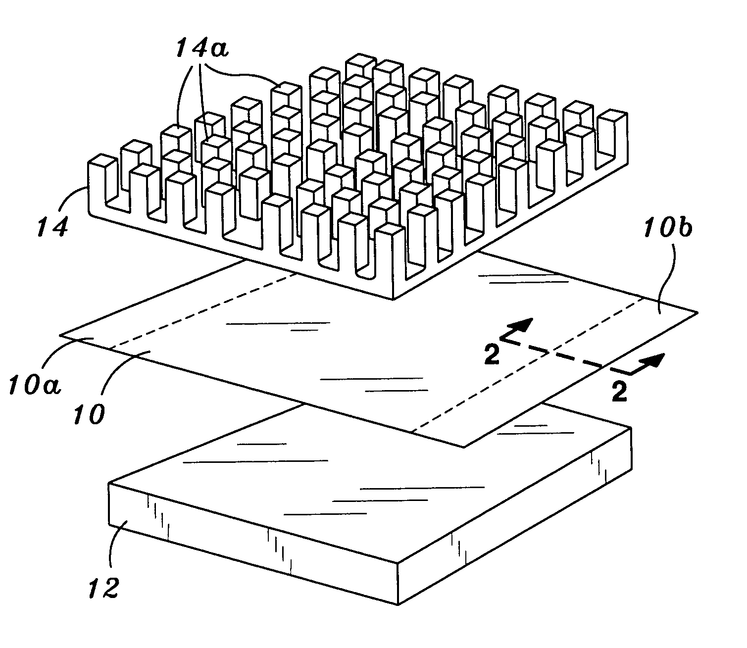
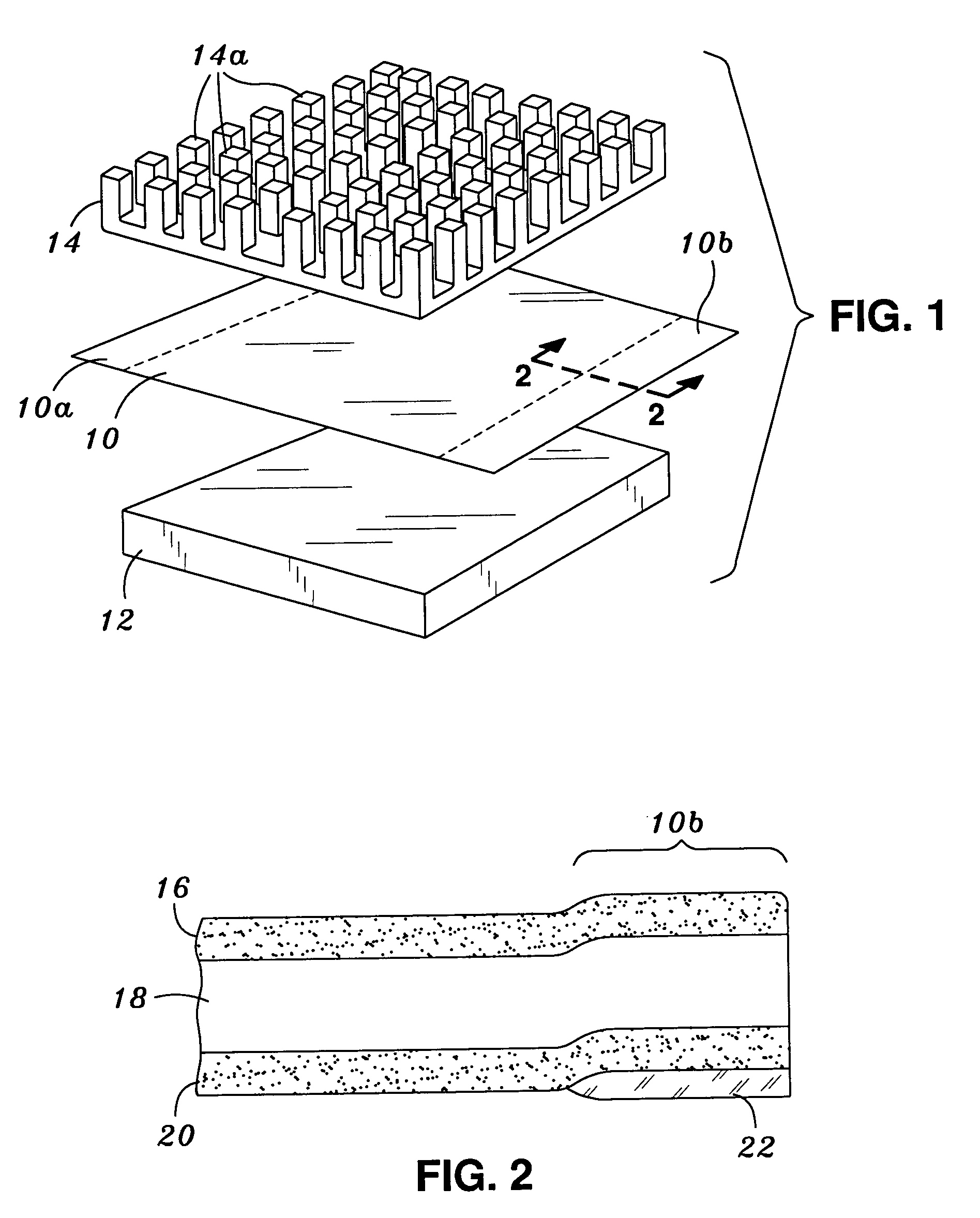
[0018]Referring now to the drawings, an initially to FIG. 1, there is shown a thermal interface 10 constructed in accordance to a preferred embodiment of the present invention. The thermal interface 10 is specifically designed and configured to facilitate the transfer of heat away from an electronic component 12 to a heat s...


PUM

PropertyMeasurementUnit
Temperatureaaaaaaaaaa
Percent by massaaaaaaaaaa

Abstract

A thermal interface for facilitating heat transfer from an electronic component to a heat sink. According to a preferred embodiment, the thermal interface comprises a first planar substrate that defines a first continuous peripheral edge, at least a portion of which extends beyond the interface mating surface between the electronic component and heat sink. Formed upon opposed sides of the substrate are layers of thermally conductive compositions, which preferably comprise certain novel graphitic allotrope compounds. The thermal interface further includes an adhesive deposited upon such portion of the peripheral edge extending beyond the mating surface between the electronic component and heat sink such that the thermal interface may be adhesively secured into position without forming an additional layer at the mating juncture between the electronic component and the heat sink.

Description

[0001]This application is a continuation of U.S. patent application Ser. No. 09 / 572,353, filed May 17, 2000 and now U.S. Pat. No. 6,616,999, the entire contents of which are incorporated by reference herein.BACKGROUND OF THE INVENTION[0002]Interface systems for use in transferring heat produced from a heat-dissipating electronic component to a heat dissipator or heat sink are well-known in the art. In this regard such electronic components, the most common being computer chip microprocessors, generate sufficient heat to adversely affect their operation unless adequate heat dissipation is provided. To achieve this end, such interface systems are specifically designed to aid in the transfer by forming a heat-conducted pathway from the components to its mounting surface, across the interface, and to the heat sink.[0003]Exemplary of such contemporary thermal interfaces are THERMSTRATE and ISOSTRATE (both trademarks of Power Devices, Inc. of Laguna Hills, Calif.). The thermstrate interfa...

Claims


Application Information

Patent Timeline
IPC IPC(8): B32B33/00B32B23/02H01L23/26B32B7/06C09K5/06F28F23/00H01L23/427
CPCB32B7/06C09K5/063F28F23/00H01L23/4275B32B2307/302F28F2013/006Y10T428/1457H01L2924/0002Y10T428/24777Y10T428/28Y10T428/2804Y10T428/14H01L2924/00
Inventor FREULER, RAYMOND G.FLYNN, GARY E.
Owner HENKEL CORP
Why Eureka
Try Eureka