Tuning a narrow band filter for telecommunication applications with an acoustic optical tunable filter

a technology of acoustic optical tunable filter and telecommunication application, which is applied in the direction of optics, semiconductor lasers, instruments, etc., can solve the problems of band filter when implemented, low channel isolation, and application of thin film filtering technology no longer practicabl

Inactive Publication Date: 2006-06-06
NEOPHOTONICS CORP
View PDF4 Cites 19 Cited by
  • Summary
  • Abstract
  • Description
  • Claims
  • Application Information

AI Technical Summary

Benefits of technology

[0006]It is therefore an object of the present invention to provide a tunable narrow band filter implemented with acoustic optical tunable filter (AOTF) technology combined with a thin film filter to achieve very narrow band tuning such that the narrow band filters are suitable for modern telecommunication system implementations.

Problems solved by technology

With evolving technology and complexity of telecommunications needs, these confronted with technical difficulties that applications of the thin film filtering technologies are no longer practical due to the requirements multiple wavelength separation and selections.
However, compared to the thin film filters, the grating based devices, despite a lower per channel cost, are usually implemented at a higher overall cost while providing lower optical performance characteristics such as rounded filter pass-band and slewed stop-band that results in low channel isolation.
Another difficulty of the convention narrow band filters when implemented in telecommunication system is the implementation of filters of fixed center wavelengths.
Due to the fact that the center wavelengths of these filters are fixed, once a telecommunication system is completed, it is extremely difficult to reconfigure or re-route network traffic.
As the high-speed network expands, so does the complication of network management and there are increased demands to reconfigure and re-route the signal transmissions.
However, these filters either lack the optical performance characteristics as demanded by the modern more complicate systems for telecommunications or lack of mechanical stability / aging / repeatability related performance characteristics.
The tunable filters as now available also are often useful only for single channel application and expensive to produce.

Method used


Image

  • Tuning a narrow band filter for telecommunication applications with an acoustic optical tunable filter
  • Tuning a narrow band filter for telecommunication applications with an acoustic optical tunable filter
  • Tuning a narrow band filter for telecommunication applications with an acoustic optical tunable filter

Examples


Embodiment Construction

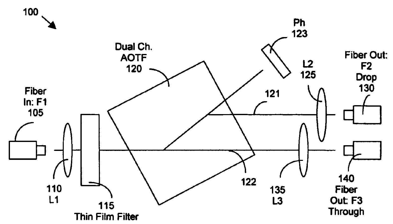
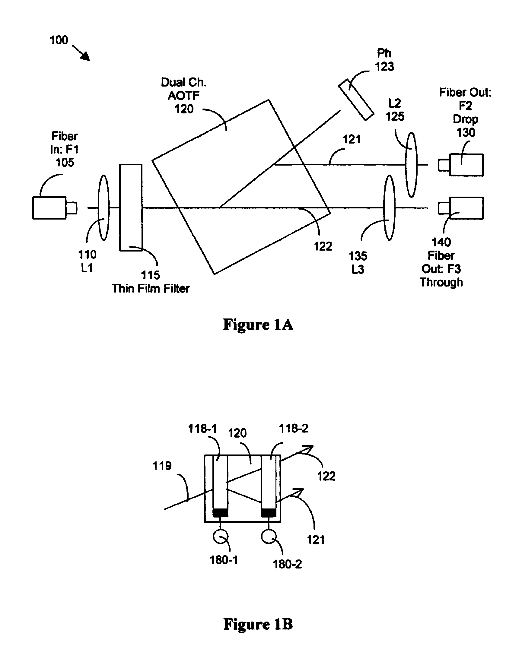
[0020]FIG. 1A shows a functional block diagram for a tunable narrow band filter 100 of the present invention. The tunable filter 100 is implemented with a dual column Acousto-optic tunable filter (AOTF) 120 and a thin film filter (TF) 110. The optical input signal is received from an optical fiber 105 and the input optical signals are collimated through a first lens 115 denoted as L1. The collimated incident beam carries all signals centered at all telecommunication ITU wavelength grids. The collimated beam then passes through the thin film filter 115 to project onto a dual column Acousto-optical tunable filter (AOTF) 120 where the first order diffraction 121 is projected from the first column and then diffracted again at the second column and then projects from the AOTF 120 through a second lens 125 denoted as L2 to generate a first output signal from the first output fiber 130 denoted as F2. The 0th order light 122 is projected from the AOTF 120 through a third lens 135, i.e, L3, ...


PUM

PropertyMeasurementUnit
sizeaaaaaaaaaa
wavelengthaaaaaaaaaa
wavelengthsaaaaaaaaaa

Abstract

An optical tunable filter that includes a thin-film filter for band-passing at least two bands of wavelengths. The tunable filter further includes a tunable band-passing device tunable over the at least two bands for tuning to a tunable pass-band spectrally overlapped with one of the at least two bands. The tunable band-passing device further includes an Acousto-optical cell tunable with acoustic wave signals. The thin-film filter cooperating with the tunable band-pass device for generating a tunable output waveform that has substantially a square waveform spectrally corresponding to the at least two bands. The thin-film filter further cooperates with the tunable band-pass device for generating a tunable output waveform having substantially a square waveform over a spectral range of a C-band, an L-band and an S-band. The tunable band-pass device band-passes a tunable substantially Sinc-function-like waveform and the thin film filter band-passing a substantially square waveform with a center attenuated dip for compensating the tunable substantially Sinc-function waveform.

Description

[0001]This is a Continuous-In-Part (CIP) Application of a previously filed Application with Ser. No. 10 / 428,899 filed on May 3, 2003 now U.S. Pat No. 6,930,819, by one of the Applicants of this invention.FIELD OF THE INVENTION[0002]The present invention relates generally to apparatuses and method for providing filters for optical fiber telecommunication systems. More particularly, this invention relates to new configurations and methods for providing tunable narrow band filters implemented with acoustic optical tunable filter and a periodical thin film filter to achieve wide and flat pass-band, sharp stop-band and at high speed and broad range tuning while providing long term reliable operations under severe operational environments.BACKGROUND OF THE INVENTION[0003]Conventional technologies of narrow band filters are typically achieved with thin film filters that are designed to have one pass-band with flat pass-band and sharp stop-band as required in telecom applications. With evol...

Claims


Application Information

Patent Timeline
Patent Type & Authority Patents(United States)
IPC IPC(8): G02F1/33G02F1/11H01S3/106H01S3/13H01S3/137H01S5/00H01S5/028H01S5/14
CPCG02F1/116H01S3/1068H01S5/141G02F1/33G02F2201/16H01S3/1305H01S5/005H01S5/0064H01S5/02284H01S5/028H01S3/137H01S5/02251
Inventor CHU, RAYMOND R.
Owner NEOPHOTONICS CORP
Why Eureka
Try Eureka