Magneto-resistive device with reduced susceptibility to ion beam damage

a magneto-resistive device and ion beam technology, applied in the field of magneto-resistive devices, can solve the problems of ion beam damage particularly from the end face, and achieve the effect of increasing the recording density of the magnetic disk apparatus and increasing the recording density

Inactive Publication Date: 2006-06-06
TDK CORPARATION
View PDF7 Cites 20 Cited by
  • Summary
  • Abstract
  • Description
  • Claims
  • Application Information

AI Technical Summary

Benefits of technology

[0033]According to the twelfth aspect, since the head suspension assembly employs the magnetic head according to the tenth or eleventh aspect, it is possible to increase the recording density of a magnetic disk apparatus and the like.
[0034]A magnetic disk apparatus according to a thirteenth aspect of the present invention includes the head ...

Problems solved by technology

It was also revealed that in a conventional magneto-resistive device, an ion beam damage reduction effect is low in an insulating layer made of Al2O3 or SiO2 disposed near a predetermined end face of the magneto-resistive laye...

Method used


Image

  • Magneto-resistive device with reduced susceptibility to ion beam damage
  • Magneto-resistive device with reduced susceptibility to ion beam damage
  • Magneto-resistive device with reduced susceptibility to ion beam damage

Examples


first embodiment

[0061]First, a magnetic head according to the present invention will be described with reference to FIGS. 1 to 5.

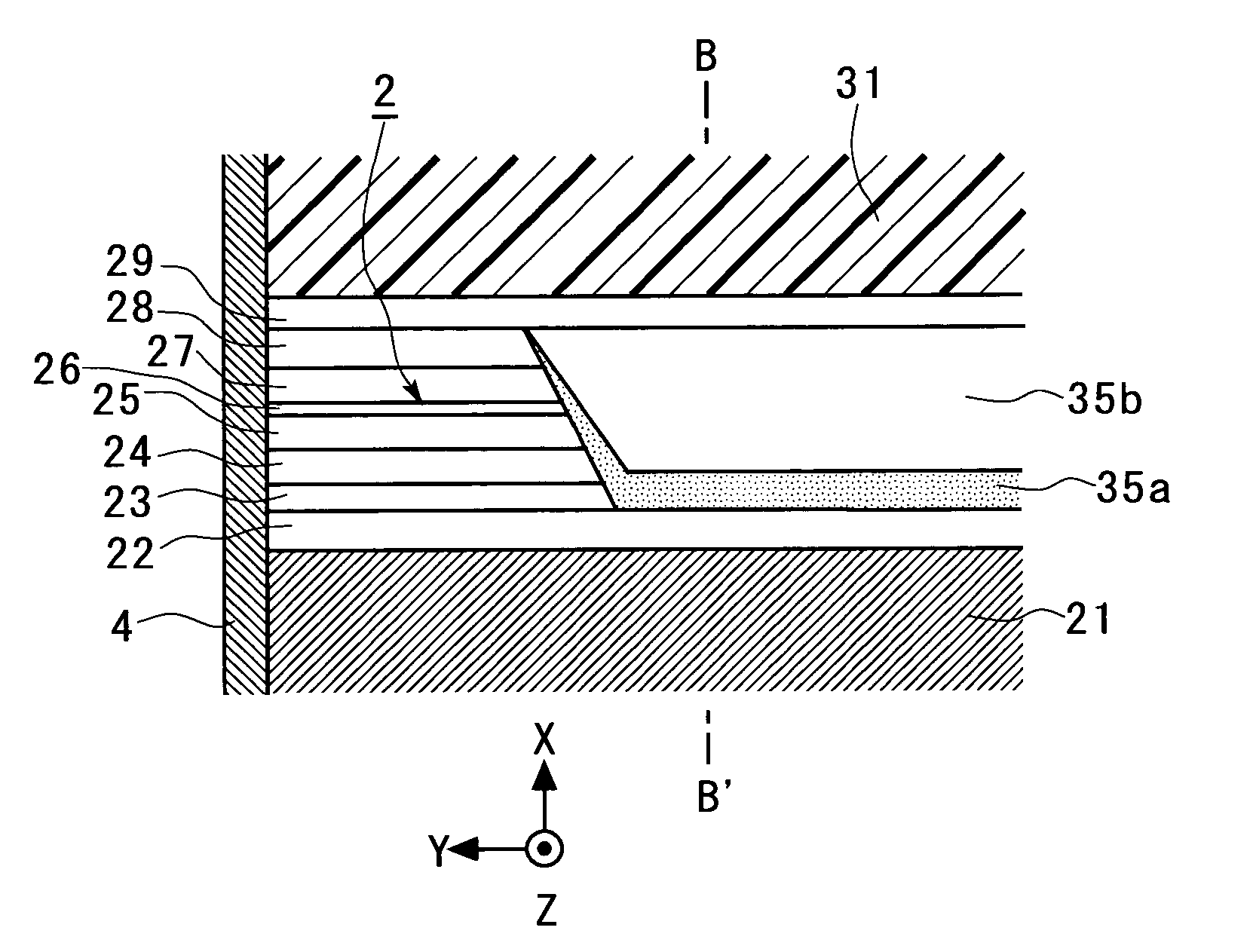
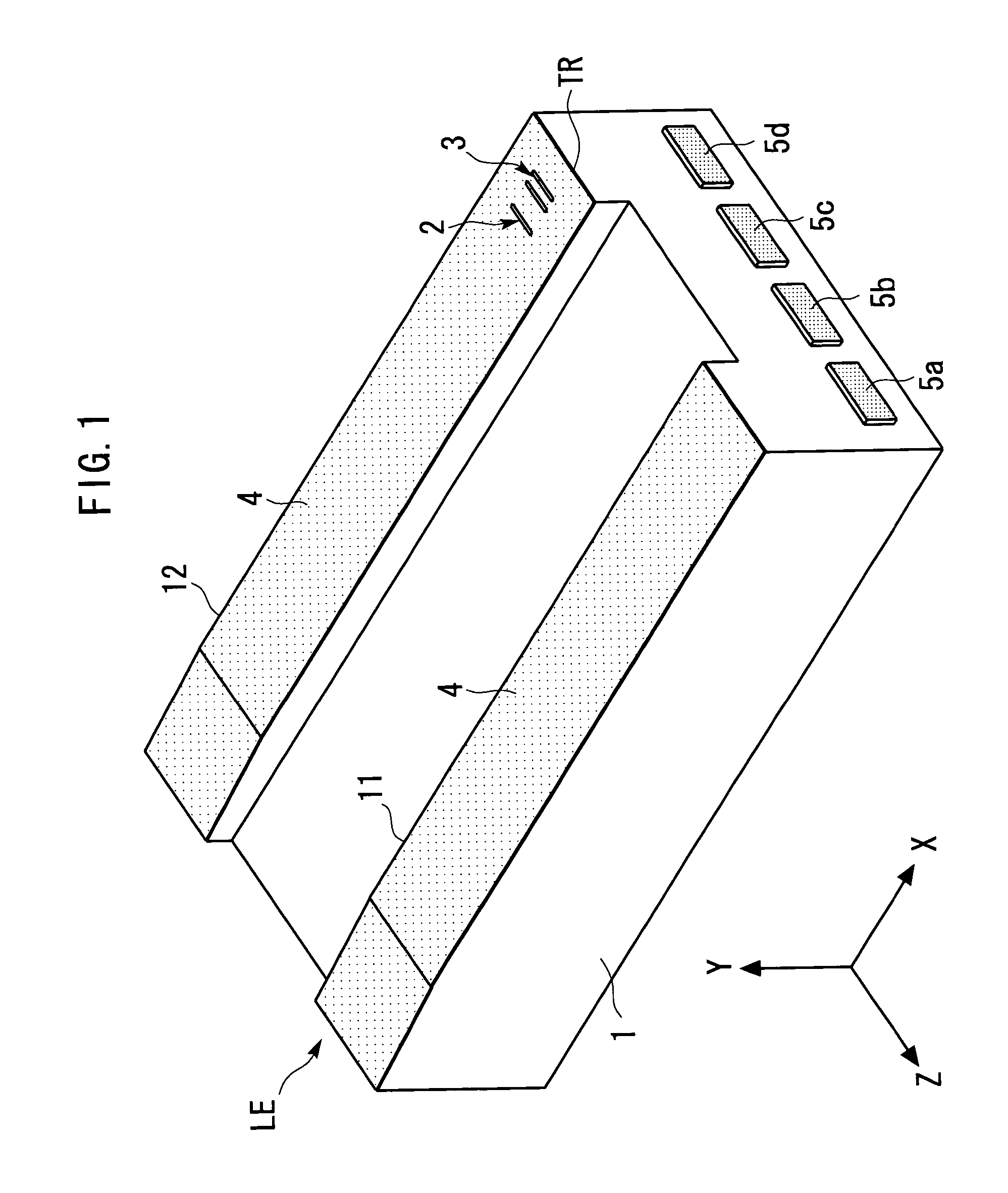
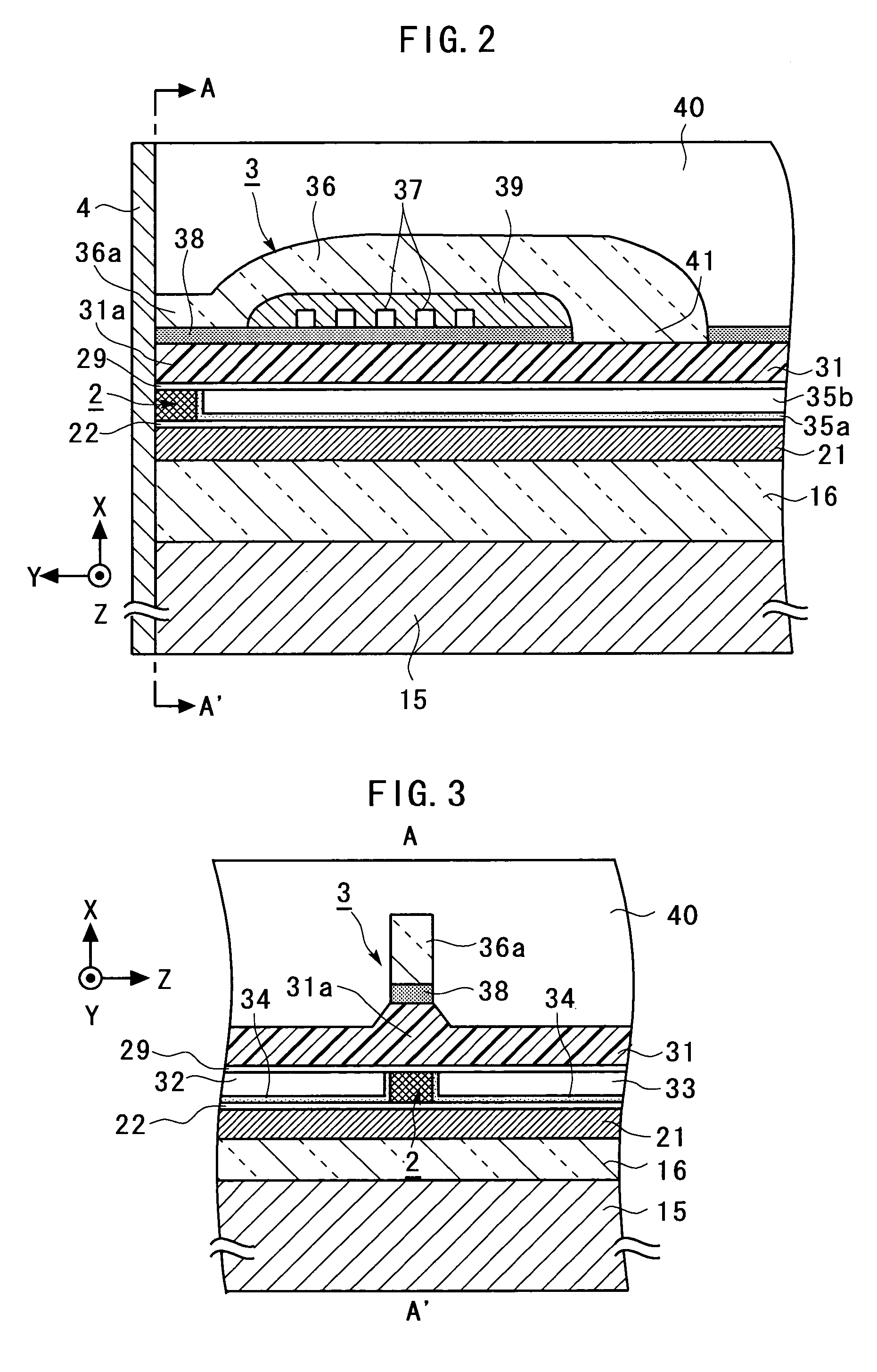
[0062]FIG. 1 is a general perspective view schematically illustrating the magnetic head according to the first embodiment of the present invention. FIG. 2 is an enlarged cross-sectional view schematically illustrating a portion of a TMR device 2 and an inductive magnetic transducing device 3 in the magnetic head illustrated in FIG. 1. FIG. 3 is a general sectional view taken along a line A–A′ indicated by arrows in FIG. 2. FIG. 4 is a further enlarged view illustrating around the TMR device 2 in FIG. 2. FIG. 5 is a further enlarged view around the TMR device 2 in FIG. 3. For facilitating the understanding, an X-axis, a Y-axis and a Z-axis, orthogonal to one another, are defined as shown in FIGS. 1 to 5 (the same applies to figures later described). The Z-axis direction indicated by the arrow is referred to as the “+Z-direction” or “+Z-side,” and the opposite direction is ...

second embodiment

[0104]Next, a magnetic head according to the present invention will be described with reference to FIGS. 16 to 20.

[0105]FIG. 16 is an enlarged cross-sectional view schematically illustrating a portion of a TMR device 2 and an inductive magnetic transducing device 3 in a magnetic head according to a second embodiment of the present invention. FIG. 17 is a general sectional view taken along a line G–G′ indicated by arrows in FIG. 16. FIG. 18 is a further enlarged view illustrating around the TMR device 2 in FIG. 16. FIG. 19 is a further enlarged view illustrating around the TMR device 2 in FIG. 17. FIG. 20 is a cross-sectional view taken along a line H–H′ in FIG. 19. FIGS. 16 to 19 correspond to FIGS. 2 to 5, respectively.

[0106]In FIGS. 16 to 20, components identical or corresponding to those in FIGS. 1 to 5 are designated by the same reference numerals, and repeated description thereon is omitted. The magnetic head according to the second embodiment differs from the magnetic head acc...

third embodiment

[0124]Now, a magnetic disk apparatus according to the present invention will be described with reference to FIG. 25.

[0125]FIG. 25 is a perspective view generally illustrating the configuration of a main portion of a magnetic disk apparatus according to a third embodiment of the present invention.

[0126]The magnetic disk apparatus according to the third embodiment comprises magnetic disks 71 rotatably mounted about a shaft 70; magnetic heads 72 each for recording and reproducing information to or from associated one of the magnetic disks 71; and an assembly carriage device 73 for positioning the magnetic head 72 on a track of the magnetic disk 71.

[0127]The assembly carriage device 73 mainly comprises a carriage 75 mounted for pivotal movements about a shaft 74; and an actuator 76 comprised, for example, of a voice coil motor (VCM) for rotating the carriage 75.

[0128]The carriage 75 is mounted with bases of a plurality of driving arms 77 which are stacked in the direction of the shaft 7...


PUM


Abstract

A magneto-resistive device is improved in characteristics by removing a surface oxide film to reduce the resistance and reducing an ion beam damage. The magneto-resistive device has a magneto-resistive layer which comprises a tunnel barrier layer, an underlying pinned layer, and an overlying free layer. A non-magnetic layer is formed on the free layer for protection. A composite-layer film comprised of an insulating layer and a damage reducing layer is formed in contact with an effective region which is effectively involved in detection of magnetism in the magneto-resistive layer without overlapping with the effective region. The damage reducing layer is made of a material which includes at least one element, the atomic weight of which is larger than that of silicon. The insulating layer and damage reducing layer do not constitute a magnetic domain control layer for applying a biasing magnetic field to the free layer.

Description

BACKGROUND OF THE INVENTION[0001]The present invention relates to a magneto-resistive device, and a magnetic head, a head suspension assembly and a magnetic disk apparatus using the same.[0002]With the trend to a larger capacity and a smaller size of hard disk drives (HDD), heads are required to have a higher sensitivity and a larger output. To meet these requirements, strenuous efforts have been made to improve the characteristics of GMR heads (Giant Magneto-Resistive Head) currently available on the market. On the other hand, intense development is under way for a tunnel magneto-resistive head (TMR head) which can be expected to have a resistance changing ratio twice or more higher than the GMR head.[0003]Generally, the GMR head differs from the TMR head in the head structure due to a difference in a direction in which a sense current is fed. A head structure adapted to feed a sense current in parallel with a film surface, as in a general GMR head, is referred to as a CIP (Current...

Claims


Application Information

Patent Timeline
IPC IPC(8): G11B5/39G11B5/31H01L43/08H01L43/10
CPCB82Y10/00B82Y25/00G11B5/3903G11B5/3909G11B5/3106G11B5/313G11B2005/3996G11B5/3967G11B5/3133
Inventor KAGAMI, TAKEOSATO, KAZUKIKANAYA, TAKAYASUSARUKI, SHUNJIKUWASHIMA, TETSUYA
Owner TDK CORPARATION
Why Eureka
Try Eureka