Motor starter device having reduced power consumption

a technology of motor starter and power consumption, which is applied in the direction of electric/dynamo-electric converter starter, single-phase induction motor starter, dynamo-electric converter control, etc., can solve the problems of inability to control the power consumption of this portion of the circuit, inability to carry out stable operation, etc., and achieve the effect of improving the power-saving motor starter devi

Active Publication Date: 2006-06-13
SENSATA TECH MASSACHUSETTS INC
View PDF24 Cites 37 Cited by
  • Summary
  • Abstract
  • Description
  • Claims
  • Application Information

AI Technical Summary

Benefits of technology

[0021]According to the motor starter device of this invention, there is provided a triac control circuit that controls the operation of the triac in conformity with the incoming current at the time of startup of the motor. Therefore, it becomes possible to directly monitor the electric current of the motor and effect the on-off control of the triac at a timing that has been synchronized with it. Moreover, it is possible to reduce the power consumption by the start winding to practically zero at the time of normal operation after the startup of the motor. A power-saving affect can be obtained by merely adding the triac control circuit, with a consequence that the cost of the motor starter can be reduced.

Problems solved by technology

However, the conventional motor starter devices described above have the following limitations.
However, because triac control PTC thermistor 250 is connected in parallel with the startup PTC thermistor 230, the current flows through triac control PTC thermistor 250 even after triac 240 has been turned off, making it impossible to control the power consumption for this portion of the circuit.
In addition, there are cases where the triac control PTC thermistor 250 can be affected by outside temperature, making it impossible to carry out stable operation.
When a re-startup is effected after an overload operation or a restrained operation, for instance, the surroundings of the motor may not be sufficiently cooled and this is especially the case during the summer.
Because of this, it is not possible to satisfactorily start the motor, making it necessary to repeat the startup procedure several times.
The time constant circuit or the trigger circuit for control of the state of conductivity of the triac is not directly responsive to the action of the motor and controlling the triac as shown in the '853 patent or the '767 patent references, with a consequence that the operation of the triac becomes unstable.
To avoid this, it becomes necessary to set the time for the triac to turn off longer which results in a problem of not being able to start the motor quickly when re-starting the motor.

Method used


Image

  • Motor starter device having reduced power consumption
  • Motor starter device having reduced power consumption
  • Motor starter device having reduced power consumption

Examples


first embodiment

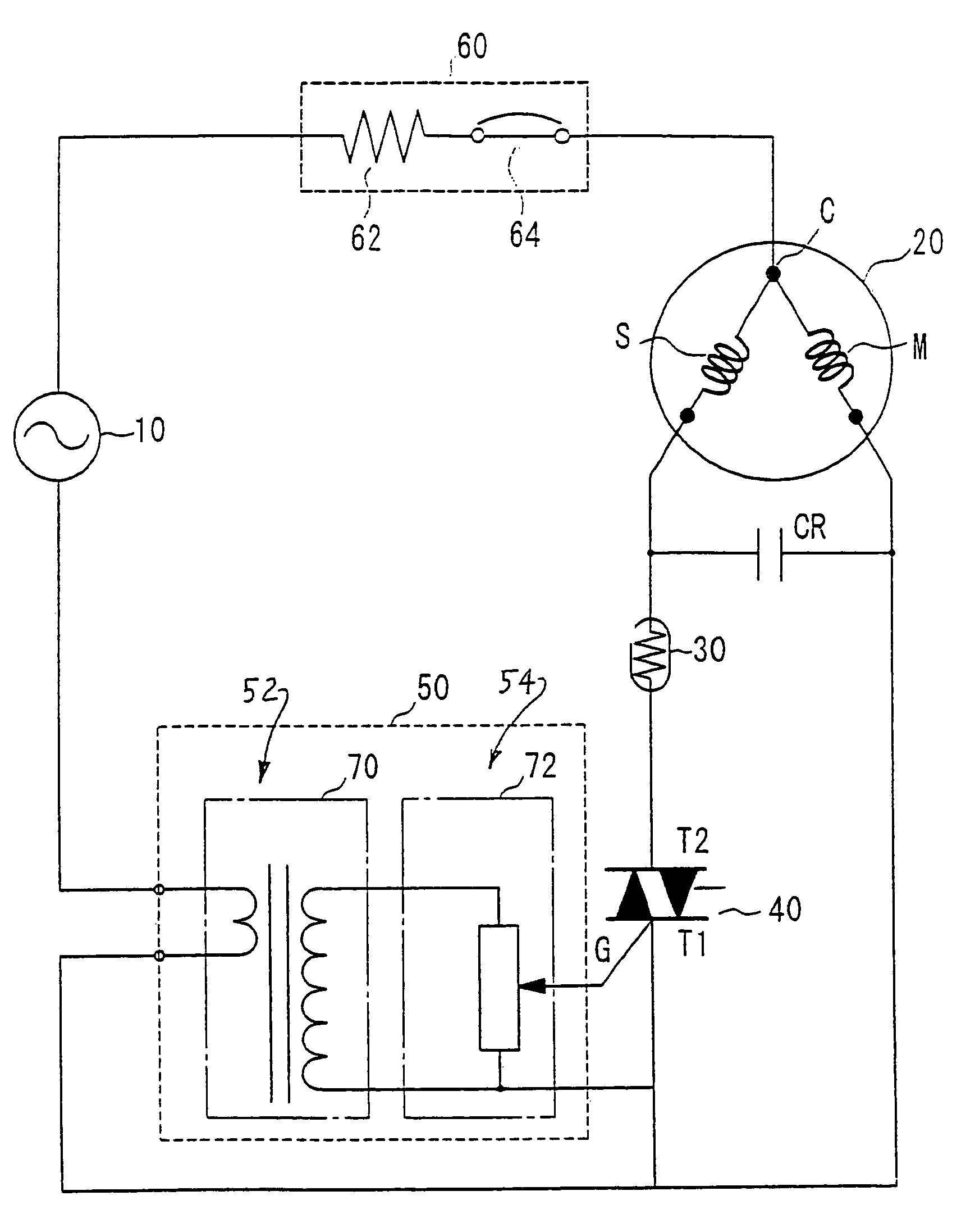
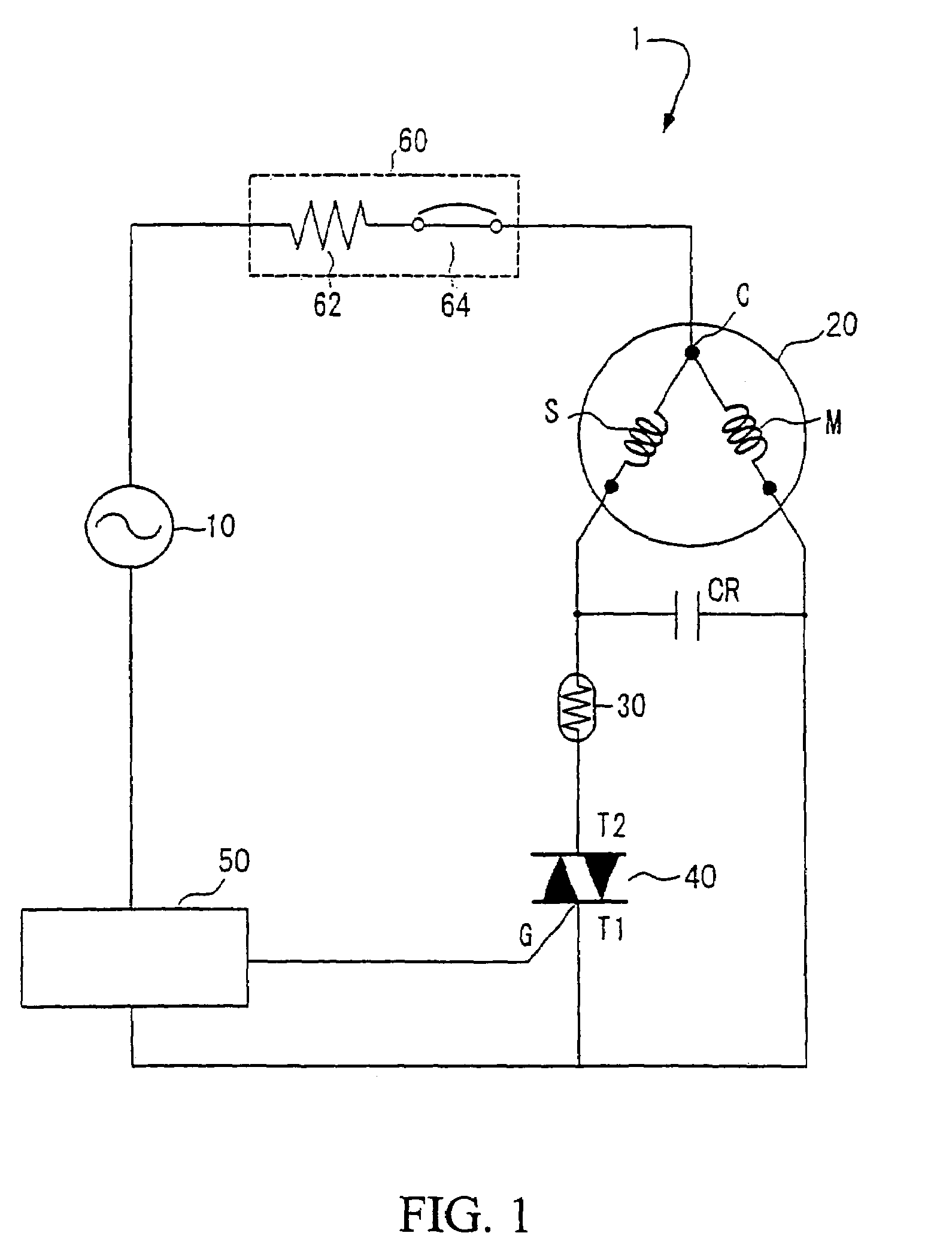
[0034]FIG. 1 shows a motor system 1 comprising the construction of a motor starter device used with a single phase induction motor 20 powered by an alternating current power source 10. The motor starter device comprises a positive coefficient of temperature thermistor (which will hereafter be referred to as a PTC thermistor) connected in series with the start winding S of motor 20, a triac 40 connected in series with PTC thermistor 30, a triac control circuit 50 connected in series with alternating current power source 10 and an overload protection device 60 connected between alternating current power source 10 and motor 20.

[0035]Motor 20 includes a main winding M and a start winding S, with the common terminal C being connected to overload protection circuit 60. A capacitor CR is connected between start winding S and main winding M for improving the efficiency of the motor. PTC thermistor 30 is provided for the purpose of sending electric current to start winding S at the time of ...

second embodiment

[0065]When the PTC thermistor for motor startup is not used, the difference between the incoming current of the motor and the current during the course of the regular operation becomes smaller. Accordingly, it becomes more difficult to set up variable resistor 82. In the second embodiment, therefore, a small-sized and highly sensitive triac has been used for first triac 90 and a comparatively large-sized one has been employed for second triac 92.

[0066]The impedance of the diode-connected transistor is approximately 0.5 volts and a voltage of about 1.5 volts is produced by means of the three transistors Tr1, Tr2 and Tr3 and a value which is extremely close to the minimum threshold voltage 1.5 V of the first triac 90 is set up. As a consequence of this, an extremely small voltage from the variable resistor 82 instantly turns triac 90 on. An amplified voltage is supplied to the gate terminal G2 of triac 92 as triac 90 is turned on, turning on triac 92 with the current flowing to the st...


PUM


Abstract

A motor starter for use with a motor (20) having a main winding (M) and a start winding (S). The starter has a PTC thermistor (30) connected in series with the start winding (S). A triac (40) is connected between PTC thermistor (30) and a power source line. A control circuit (50) is connected to the power source line for providing a voltage for a gate terminal (G) of triac (40) and an overload relay (60) is connected between the power source (10) and the motor (20). The control circuit (50) preferably includes a current detecting circuit (52) for detecting the inrush current and a voltage generating circuit (54) for generating the voltage in response to the detected inrush current. At the startup of motor (20) the control circuit (50) allows triac (40) to turn on by providing the gate terminal (G) with the voltage based on the inrush current. According to this invention, the power consumption of the start winding S after the startup of the motor (20) can be almost zero thus providing low power consumption. In another embodiment not employing a PTC thermistor, a current detecting circuit and a voltage generating circuit are used to control the on and off states of a first triac (90) which in turn controls the on and off states of a second triac (92) connected in series with the start winding.

Description

FIELD OF THE INVENTION[0001]This invention relates generally to motor starter devices for starting motors such as a single phase induction motor and more particularly to motor starter devices with reduced power consumption employing a triac for the startup control of the motor.RELATED APPLICATIONS[0002]Priority is claimed under 35 U.S.C. Section 119 of Japanese Patent Application No. 2004-048420 filed Feb. 24, 2004.BACKGROUND OF THE INVENTION[0003]A conventional motor starter device for a refrigerator or air conditioner compressor is shown in FIG. 8 along with motor 100 having a start winding S, a main winding M and a common terminal C. A positive temperature coefficient of resistivity thermistor (PTC) 110 is connected in series to start winding S and an overload protection device 120 is connected to terminal C. An operating capacitor CR is connected between start winding S and main winding M for increasing the efficiency of the motor.[0004]During startup of the motor, sufficient cu...

Claims


Application Information

Patent Timeline
Patent Type & Authority Patents(United States)
IPC IPC(8): H02P1/42H02P1/44
CPCH02P1/44H02P1/423H02P1/42H02P1/48
Inventor UNNO, MITSURU
Owner SENSATA TECH MASSACHUSETTS INC
Why Eureka
Try Eureka