Measuring sensor utilizing attenuated total reflection and measuring chip assembly
a technology of attenuated total reflection and measuring chip, which is applied in the direction of instruments, specific use bioreactors/fermenters, biomass after-treatment, etc., can solve the problems of inability to accurately measure the temporal change and so as to prevent the evaporation of liquid samples and enhance the measurement accuracy of the state of atr
- Summary
- Abstract
- Description
- Claims
- Application Information
AI Technical Summary
Benefits of technology
Problems solved by technology
Method used
Image
Examples
first embodiment
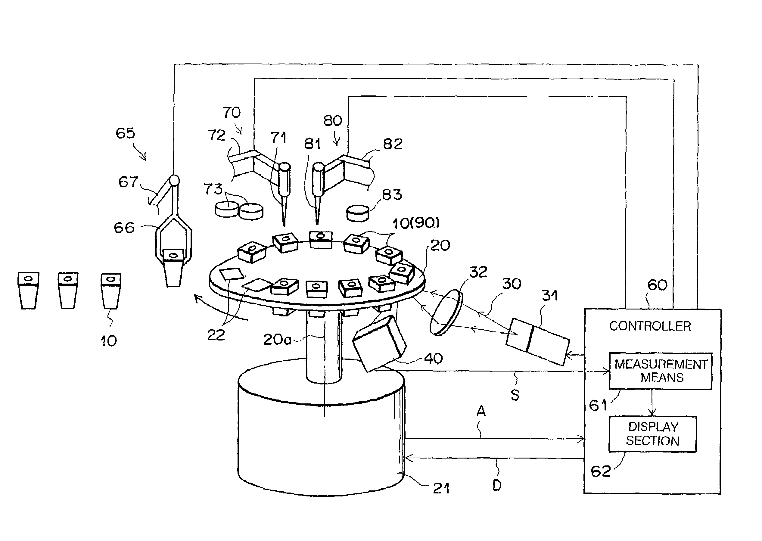
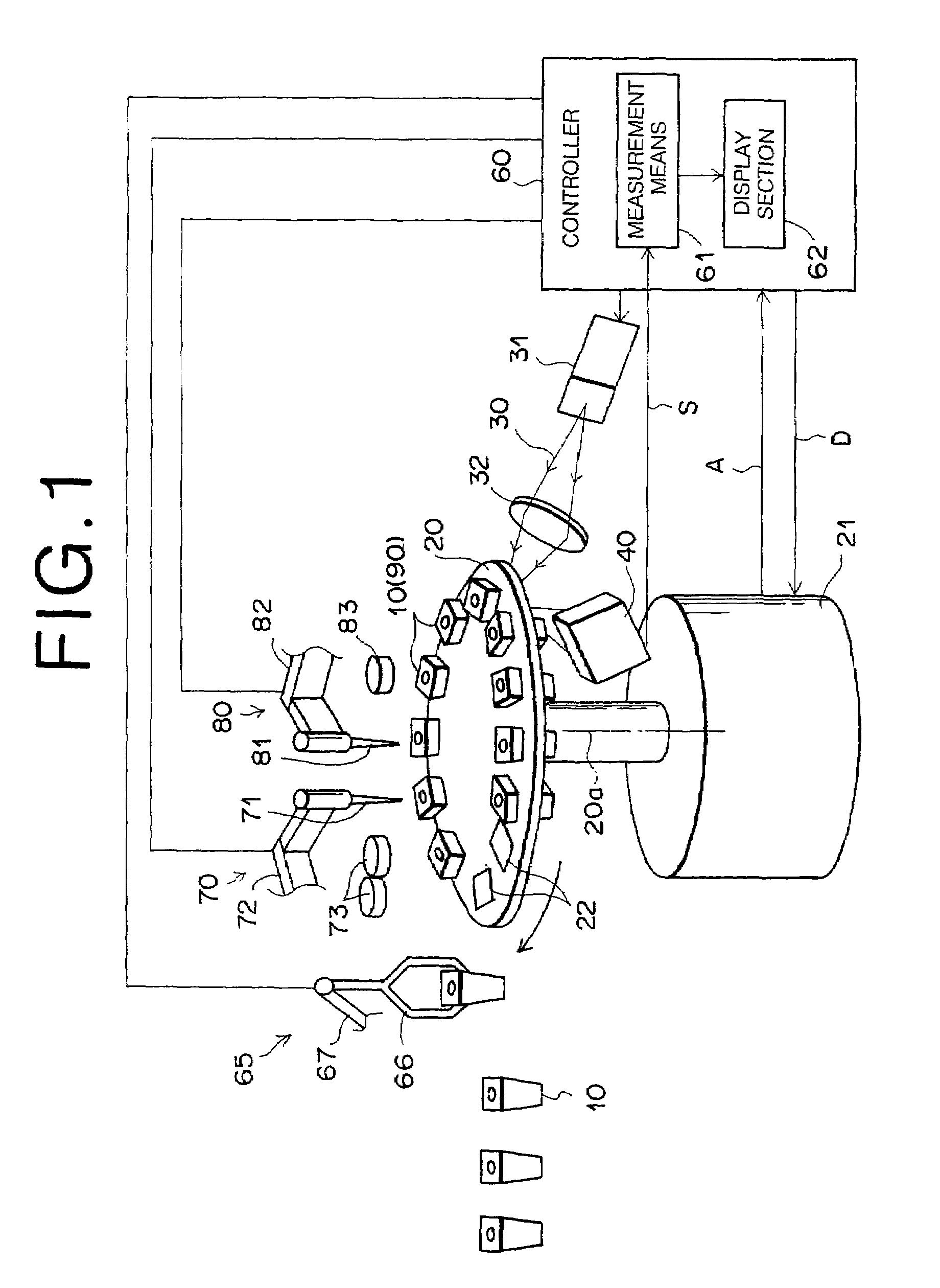
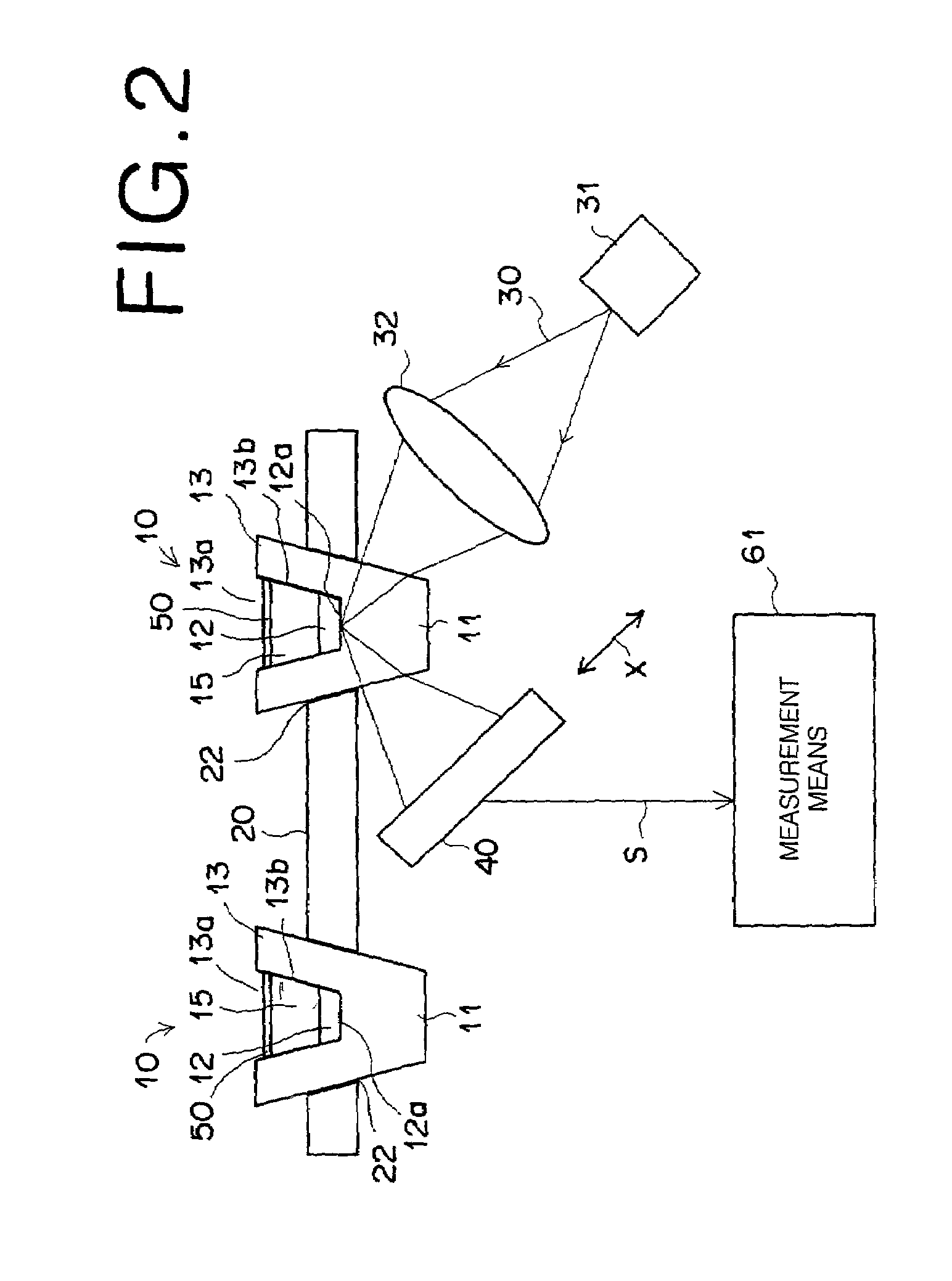
[0088]FIG. 1 shows a surface plasmon resonance sensor constructed according to the present invention, and FIG. 2 shows a side view of the essential parts thereof. As shown in the figures, the surface plasmon resonance sensor has a plurality of measuring units 10; a turntable 20 for supporting the measuring units 10; and supporting-body drive means (movement means) 21 for rotating the turntable 20 intermittently. The surface plasmon resonance sensor also has a laser light source 31, such as a semiconductor laser, etc., for emitting a measuring light beam (e.g., a laser beam) 30; condenser lens 32 constituting an optical incidence system; and a photodetector 40. The surface plasmon resonance sensor further has a controller 60 for controlling the laser light source 31 and the supporting-body drive means 21; a measuring-unit supply mechanism 65 for supplying or removing the measuring unit 10 to or from the turntable 20; and a liquid-sample supply mechanism 70. The controller 60 receives...
second embodiment
[0109]FIGS. 4 and 5 show a surface plasmon resonance sensor constructed according to the present invention. Note in FIG. 4 that the same reference numerals are applied to the same parts as those in FIG. 1, and that a description of the same parts will not be given unless particularly necessary.
[0110]In the surface plasmon resonance sensor of the second embodiment, a lid supply mechanism 84 to cover the opening 13a of the liquid-sample holding portion 13b of a measuring unit 10 with a lid 51 is employed as lid-means supply means. The lid 51, as shown in FIG. 5, is a square lid with a protruding portion 52 in the form of a truncated cone at the center. The protruding portion 52 is slightly smaller in diameter than the opening 13a of the liquid-sample holding portion 13b. One side of the square of the lid 51 is equal to the length of one side of the top surface of the liquid-sample holder 13. The lid supply mechanism 84 is constructed of a holding portion 85 for holding the lid 51 and ...
third embodiment
[0116]FIGS. 9 and 10 show a surface plasmon resonance sensor constructed according to the present invention. Note in FIG. 10 that the same reference numerals are applied to the same parts as those in FIG. 1, and that a description of the same parts will not be given unless particularly necessary.
[0117]In the surface plasmon resonance sensor of the third embodiment, a lid supply mechanism 87 to cover the opening 13a of the liquid-sample holding portion 13b of a measuring unit 10 with a lid 53 is employed as lid supply means before the measuring unit 10 is disposed on a turntable 20. The lid 53, as shown in FIGS. 10A and 10B, is a square lid with a protruding portion 54 in the form of a truncated cone at the center. The protruding portion 54 is slightly smaller in diameter than the opening 13a of the liquid-sample holding portion 13b. One side of the square of the lid 53 is equal to the length of one side of the top surface of the liquid-sample holder 13. The protruding portion 54 is ...
PUM
 Abstract
Description
Claims
Application Information
 - R&D
- Intellectual Property
- Life Sciences
- Materials
- Tech Scout
- Unparalleled Data Quality
- Higher Quality Content
- 60% Fewer Hallucinations
Browse by: Latest US Patents, China's latest patents, Technical Efficacy Thesaurus, Application Domain, Technology Topic, Popular Technical Reports.
© 2025 PatSnap. All rights reserved.Legal|Privacy policy|Modern Slavery Act Transparency Statement|Sitemap|About US| Contact US: help@patsnap.com


