

Low evaporative emission fuel system depressurization via solenoid valve
a fuel system and evaporative emission technology, applied in the direction of fuel injection apparatus, charge feed system, fuel addition of non-fuel substances, etc., can solve the problems of fuel injectors, fuel leakage is exacerbated, fuel leakage is typically encapsulated, etc., to minimize fuel leakage and evaporative emissions, prevent pressure buildup, and minimize the effect of fuel pressure increas
- Summary
- Abstract
- Description
- Claims
- Application Information
AI Technical Summary
Benefits of technology
Problems solved by technology
Method used
Image

Examples
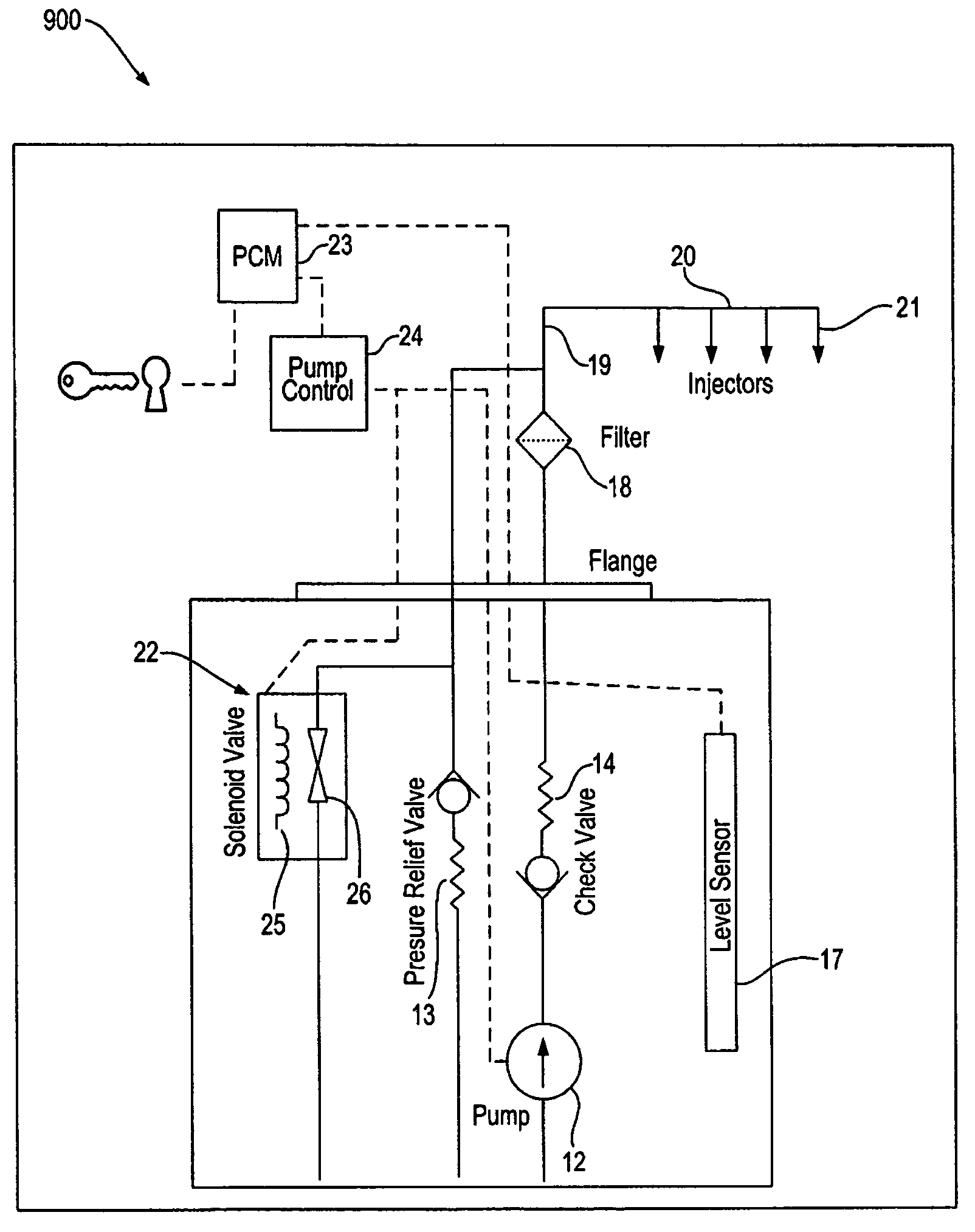
embodiment 900
[0065]In another aspect of the MFRS embodiment 900, another corresponding control method opens the solenoid valve 22 after a given lapse of time from key-off, inferring that a cool-off has occurred. This other control method is substantially similar to the control method depicted in FIG. 6 via flow chart 600.
[0066]In another aspect of the MFRS 900, another corresponding control method opens the solenoid valve 22 when the fuel delivery system 10 senses a desired fuel temperature, inferring that a fuel's vapor pressure has dropped below atmospheric temperature. This other control method is substantially similar to the control method depicted in FIG. 7 via flow chart 700.
[0067]In another aspect of the MFRS 900, another corresponding control method allows or waits for the fuel delivery system 10 to cool-down before the solenoid valve 22 is opened when the fuel pressure is either above 2.5 psi or below −0.5 psi. This other control method is substantially similar to the control method dep...
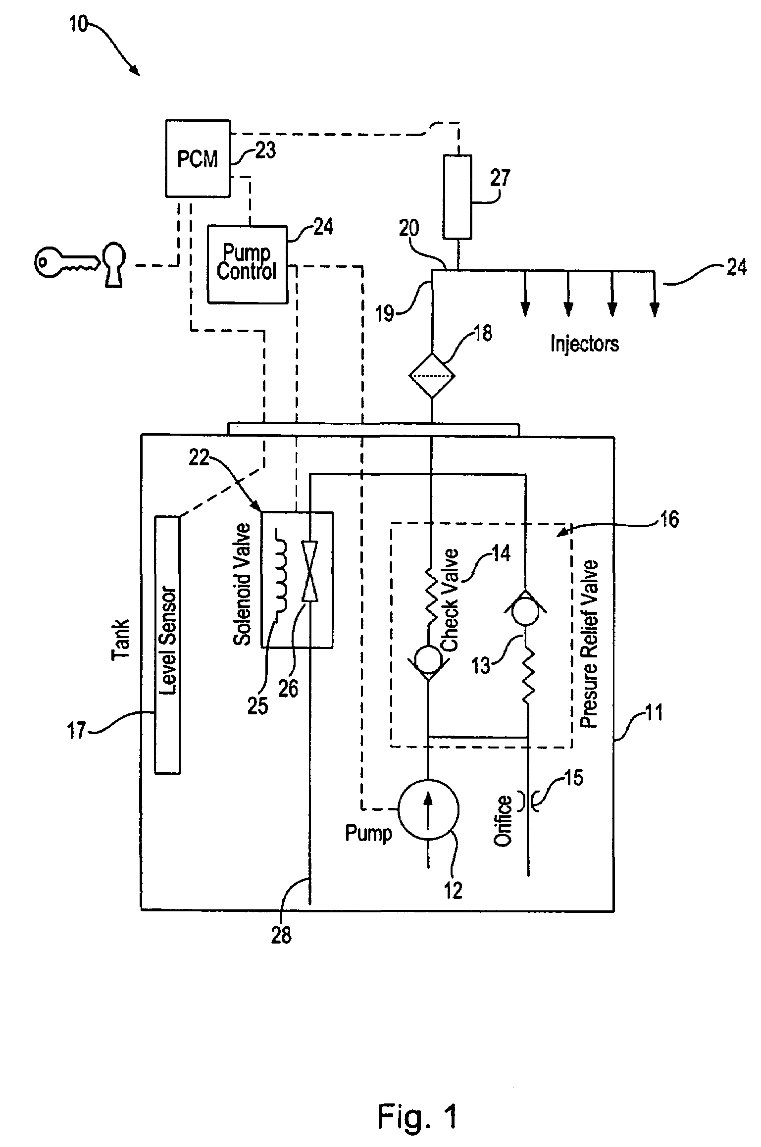
embodiment 10
[0070]Alternately, the ERFS 1000 is provided with the solenoid valve 22 normally closed. Correspondingly, further aspects of this ERFS 1000 may be provided with alternate control methods of the solenoid valve 22 that are substantially similar to the control methods described in conjunction with the alternate aspects of the previously discussed fuel delivery system embodiment 10. Thereafter, this method ends at step 1110.
[0071]Referring to FIG. 12, another MRFS 1200 with the solenoid fuel valve 22 is shown. In this embodiment, the fuel solenoid valve 22 is connected in the MRFS 1200 on the filtered side of the fuel delivery system, with another pressure relief valve 1002 positioned between the solenoid valve 22 and the fuel tank 11. Similar alternate aspects discussed above in relation to the ERFS 1000 may be provided to this MRFS 1200 with the solenoid valve 22 either normally closed or normally open. Correspondingly, alternate control methods of the solenoid valve 22 are substantia...
PUM
 Abstract
Description
Claims
Application Information