Method and means for miniaturization of binary-fluid heat and mass exchangers

a technology of heat and mass exchangers and microfluids, which is applied in the direction of milk preservation, lighting and heating apparatus, and separation processes, etc., can solve the problems of large components, low heat and mass transfer rate, and low coefficient of performance of these thermodynamic cycles, so as to promote facilitate high heat and mass transfer rates , the effect of high wettability of the transfer surfa

Inactive Publication Date: 2006-06-27
IOWA STATE UNIV RES FOUND
View PDF57 Cites 11 Cited by
  • Summary
  • Abstract
  • Description
  • Claims
  • Application Information

AI Technical Summary

Benefits of technology

[0010]This invention addresses the deficiencies of currently available designs. It is an extremely simple geometry that is widely adaptable for a variety of miniaturized absorption system components. It can be used for fluid pairs with non-volatile and volatile absorbents. It promotes high heat and mass transfer rates through flow mechanisms such as counter-current vapor-liquid flow, vapor shear, droplet entrainment, adiabatic absorption between tubes, species concentration redistribution due to liquid droplet impingement, significant interaction between vapor and liquid flow around adjacent tubes in the transverse and vertical directions, and other deviations from idealized falling films. It ensures uniform distribution of the liquid and vapor films and high wettability of the transfer surfaces.
[0011]Short lengths of very small diameter tubes are placed in a square array, with several such arrays being stacked vertically. Successive tube arrays are oriented in a transverse orientation perpendicular to the tubes in adjacent levels. In an absorber application, the liquid solution flows in the falling-film mode counter-current to the coolant through the tube rows. Vapor flows upward through the lattice formed by the tube banks, counter-current to the falling solution. The effective vapor-solution contact minimizes heat and mass transfer resistances, the solution and vapor streams are self-distributing, and wetting problems are minimized. Coolant-side heat transfer coefficients are extremely high without any passive or active surface treatment or enhancement, due to the small tube diameter.

Problems solved by technology

Several studies have shown that the high coefficients of performance of these thermodynamic cycles cannot be realized without the development of practically feasible and compact heat exchangers.
While significant research has been done on absorption cycle simulation, innovations in component development have been rather sparse, in spite of the considerable influence of component performance on system viability.
Successful designs for such binary fluid heat and mass exchangers must address the following often contradictory requirements:low heat and mass transfer resistances for the absorption / desorption side.adequate transfer surface area on both sides.low resistance of the coupling fluid—designs have been proposed in the past that enhance absorption / desorption processes, but fail to reduce the single-phase resistance on the other side, resulting in large components.low coupling fluid pressure drop—to reduce parasitic power consumption.low absorption side pressure drop—this is essential because excessive pressure drops, encountered in forced-convective flow at high mass fluxes, decrease the saturation temperature and temperature differences between the working fluid and the heat sink.

Method used


Image

  • Method and means for miniaturization of binary-fluid heat and mass exchangers
  • Method and means for miniaturization of binary-fluid heat and mass exchangers
  • Method and means for miniaturization of binary-fluid heat and mass exchangers

Examples


Embodiment Construction

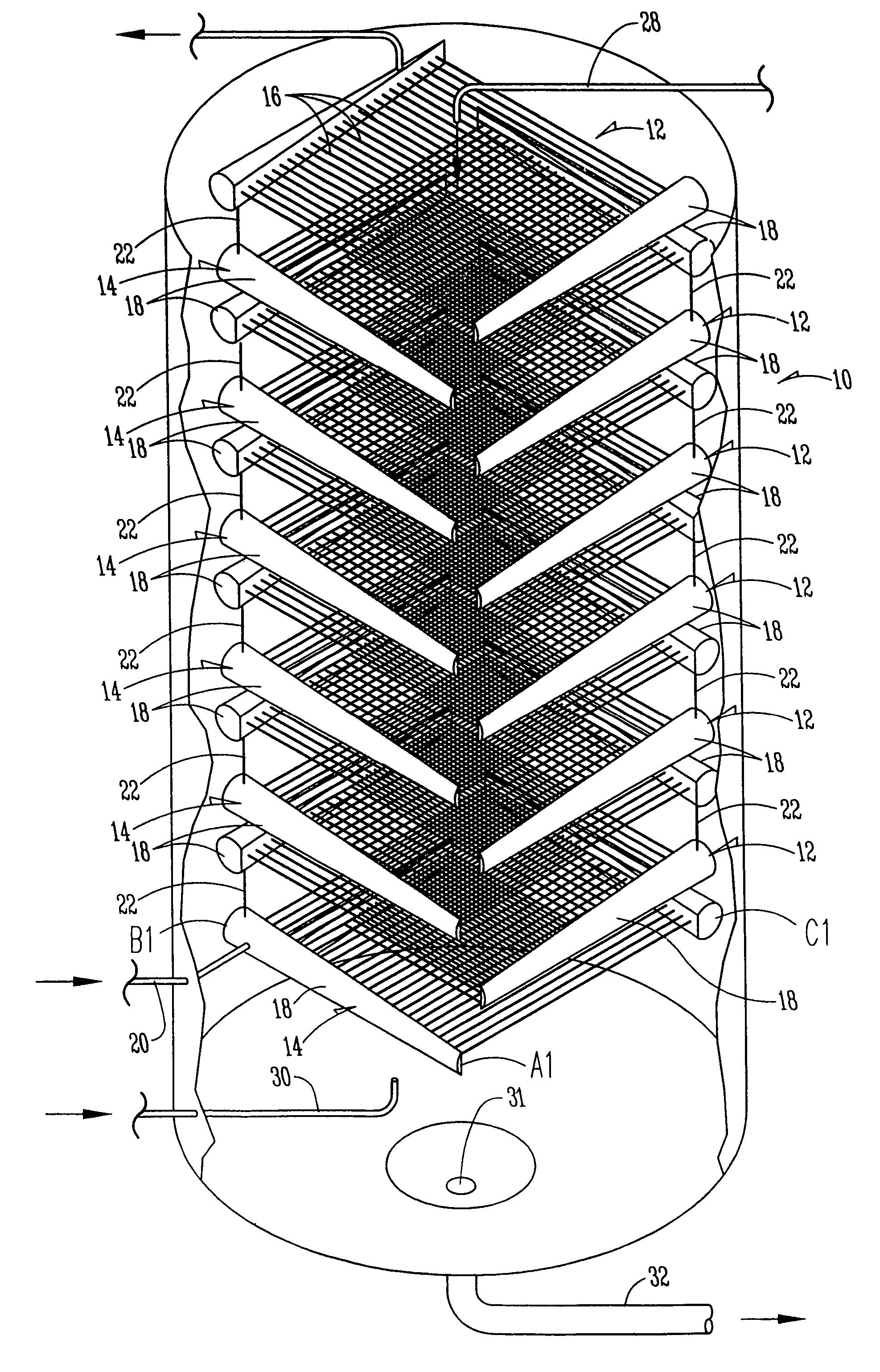
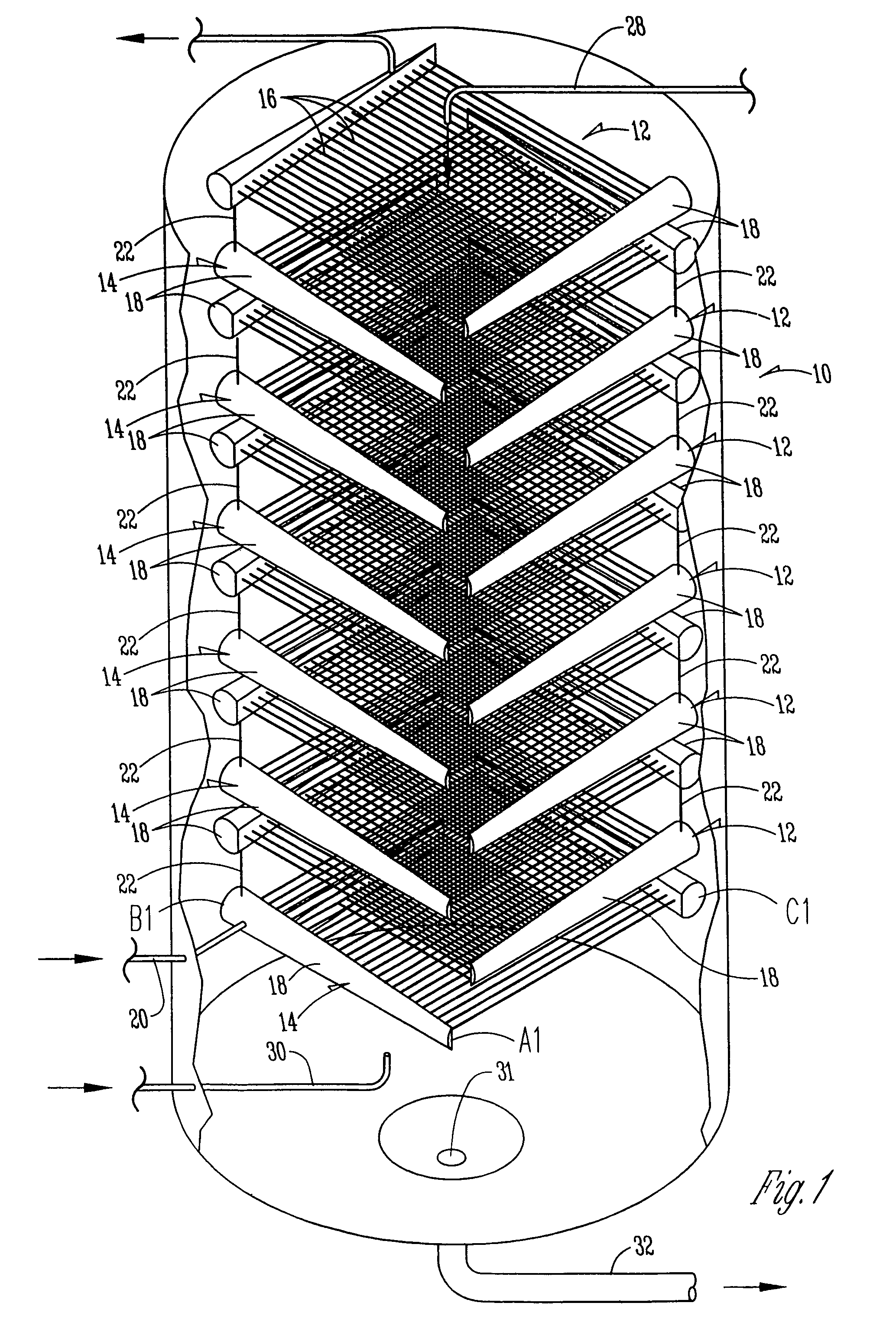
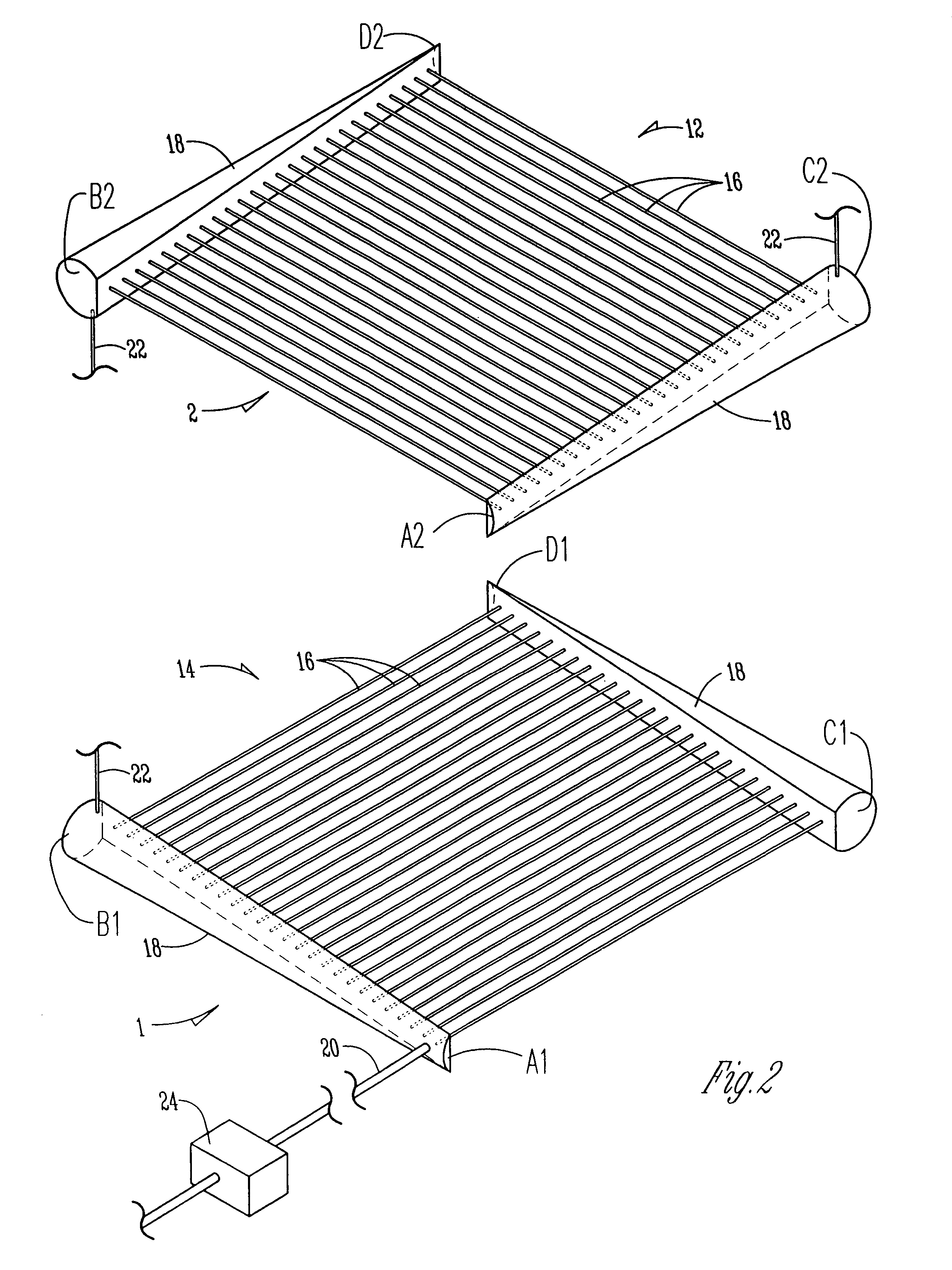
[0020]With reference to FIG. 1, the numeral 10 designates a support structure wherein alternate groups of coolant tubes 12 and 14 (FIG. 1) are mounted in spaced vertical relation in structure 10. Each group 12 and 14 is comprised of a plurality of small diameter coolant tubes 16 which extend between opposite headers 18. (FIGS. 1 and 2). The orientation of the tubes 16 in group 12 is at right angles to the orientation of tubes 16 in group 14 (FIG. 2). The tubes 16 in each group are in fluid communication with headers 18.

[0021]Hydronic fluid is introduced into the lowermost group of tubes at 20 (FIG. 1), and successive groups are fluidly connected by conduits 22.

[0022]The short lengths of very thin tubes 16 (similar to hypodermic needles) are placed in an approximately square array. This array forms level 1 (FIG. 2), depicted by the square A1-B1-C1-D1. The second array (level 2) of thin tubes 16 is placed above level 1, but in a transverse orientation perpendicular to the tubes in lev...


PUM

PropertyMeasurementUnit
diameteraaaaaaaaaa
diameteraaaaaaaaaa
diameteraaaaaaaaaa

Abstract

A binary-fluid heat and mass exchanger has a support structure with a plurality of horizontal vertically spaced groups of tubes mounted thereon. Each group of tubes comprises a pair of horizontal spaced hollow headers. A plurality of small diameter hollow tubes extend between the headers in fluid communication therewith. Fluid conduits connect a header of one group of tubes with a header of an adjacent group of tubes so that all of the groups of tubes will be fluidly connected. An inlet port for fluid is located on a lower group of tubes, and an exit port for fluid is connected to a higher tube group to permit fluid to flow through the tubes in all of the groups. A second inlet port for introducing a solution of fluid downwardly over the tubes is located above the support structure. An outlet port is located at the top of the support structure to convey generated vapor upwardly through the groups and out of the heat exchanger. A fluid exit port is located below the support structure for the removal of fluid collected from the various groups of tubes.

Description

CROSS REFERENCE TO RELATED APPLICATIONS[0001]This application is a continuation-in-part of application Ser. No. 09 / 669,056 filed Sep. 25, 2000, now U.S. Pat. No. 6,802,364 which is a continuation of application Ser. No. 09 / 253,155 filed Feb. 19, 1999 now abandoned.BACKGROUND OF THE INVENTION[0002]Absorption heat pumps are gaining increased attention as an environmentally friendly replacement for the CFC-based vapor-compression systems that are used in residential and commercial air-conditioning. These heat pumps rely heavily on internal recuperation to yield high performance. Several studies have shown that the high coefficients of performance of these thermodynamic cycles cannot be realized without the development of practically feasible and compact heat exchangers. While significant research has been done on absorption cycle simulation, innovations in component development have been rather sparse, in spite of the considerable influence of component performance on system viability....

Claims


Application Information

Patent Timeline
Patent Type & Authority Patents(United States)
IPC IPC(8): B01F3/04F25B37/00F28D7/16F28F9/02
CPCF25B37/00F28F9/0263F28F9/02F28D7/1615
Inventor GARIMELLA, SRINIVAS
Owner IOWA STATE UNIV RES FOUND
Why Eureka
Try Eureka