Systems and methods for measurement or analysis of a specimen using separated spectral peaks in light

a technology of spectral peaks and specimens, applied in the direction of optical radiation measurement, instruments, spectrometry/spectrophotometry/monochromators, etc., can solve the problems of severe reduction of the imaging capability of the optical system, insufficient amount of light available for imaging resists on wafers, and significant problems for these systems, so as to increase the accuracy of measurements

Active Publication Date: 2006-06-27
KLA TENCOR TECH CORP
View PDF45 Cites 81 Cited by
  • Summary
  • Abstract
  • Description
  • Claims
  • Application Information

AI Technical Summary

Benefits of technology

[0040]Partitioning of the data may maintain a wavelength calibration of the detector. Partitioning of the data may also increase an accuracy of the measurements of the optical subsystem that are performed as a function of wavelength. In addition, partitioning of the data may correct for spectrum shift, drift, stretching, shrinking, or a combination thereof at the detector.

Problems solved by technology

In contrast, as the wavelength of optical systems falls below 190 nm, absorption of the light by water, oxygen, and air can cause significant problems for these systems.
For instance, in lithography tools designed for use at 157 nm, the amount of light available for imaging a resist on a wafer may be insufficient due to the absorption of the light by air in the lithography tool.
Therefore, any absorption of the light by the environment in the lithography tool can result in a severe reduction in the imaging capability of the optical system.
Since generating and maintaining a vacuum can be relatively expensive, however, more common methods for reducing absorption of light having wavelengths less than 190 nm involve purging the housing in which the optical components and the specimen are placed.
There are, however, several problems with the current methods that are used to purge optical systems.
In addition, purging a large region of the tool takes a significant amount of time.
Therefore, purging can have a significant adverse impact on the throughput of the optical system.

Method used


Image

  • Systems and methods for measurement or analysis of a specimen using separated spectral peaks in light
  • Systems and methods for measurement or analysis of a specimen using separated spectral peaks in light
  • Systems and methods for measurement or analysis of a specimen using separated spectral peaks in light

Examples


Embodiment Construction

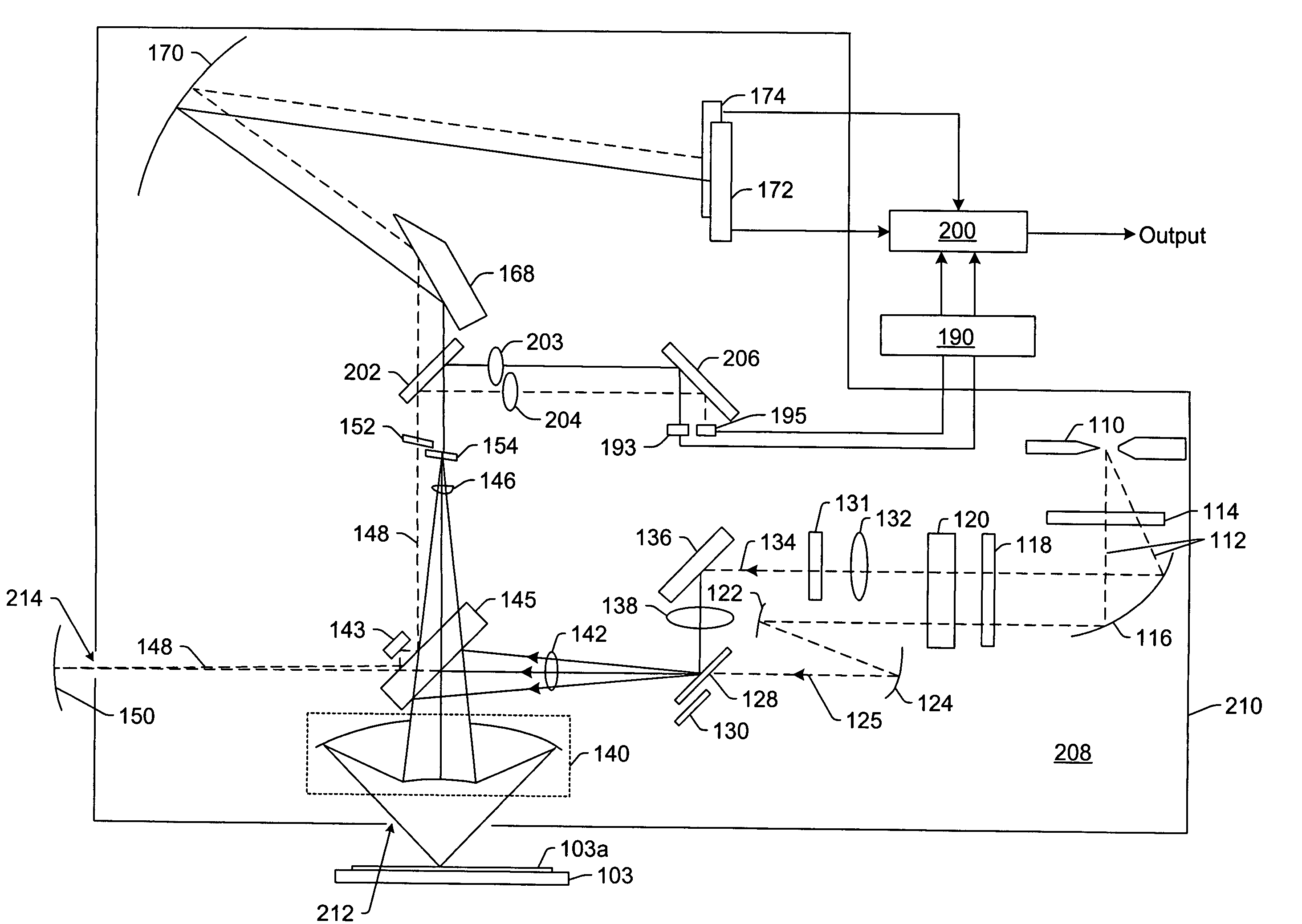
[0068]The following description generally relates to optical systems configured to operate at wavelengths which advantageously use a purged environment. By purging only those optical subsystems that actually benefit from purging, cost can be saved, and reliability can be improved. The embodiments described herein could be very important to economically manufacturing systems that operate at relatively low wavelengths (e.g., vacuum ultraviolet or near vacuum ultraviolet wavelengths). For example, the alternative is to enclose the whole system in a chamber filled with an inert gas (or vacuum) with a load lock to allow loading and unloading of specimens without introducing too much oxygen, water, carbon dioxide, etc. Such an approach results in slower wafer transfer, more restricted access to the optics for alignment, and makes the system more expensive.

[0069]As used herein, the term “specimen” generally refers to a wafer or a reticle. As used herein, the term “wafer” generally refers t...


PUM

PropertyMeasurementUnit
wavelengthsaaaaaaaaaa
wavelengthaaaaaaaaaa

Abstract

A system configured for measurement of a specimen is provided. The system includes an optical subsystem configured to perform measurements of the specimen. The optical subsystem includes a light source that is configured to generate light having a relatively large number of separated spectral peaks with substantially no continuous background. In some embodiments, the light may include vacuum ultraviolet light, extreme ultraviolet light, and / or soft x-rays. A carrier medium is also provided that includes program instructions executable on a computer system to analyze data generated by a detector of an optical subsystem by partitioning the data into individual peaks spaced apart across a wavelength spectrum. Partitioning the data preferably corrects for spectrum shift, drift, stretching, shrinking, or a combination thereof at the detector. The individual peaks correspond to separated spectral peaks in light generated by a light source of the optical subsystem.

Description

BACKGROUND OF THE INVENTION[0001]1. Field of the Invention[0002]The present invention generally relates to systems and methods for measurement or analysis of a specimen using separated spectral peaks in light. Certain embodiments relate to a system configured for measurement of a specimen that includes a light source configured to generate light having a relatively large number of separated spectral peaks with substantially no continuous background.[0003]2. Description of the Related Art[0004]Optical systems play a significant role in the manufacturing of integrated circuits and other semiconductor devices. For example, optical lithography tools are used to transfer a pattern from a reticle to a resist coated wafer. The patterned features on the wafer can then be used to form various features of integrated circuits and semiconductor devices. In addition, optical metrology and / or inspection tools are used for quality control purposes in semiconductor manufacturing. The capability and...

Claims


Application Information

Patent Timeline
Patent Type & Authority Patents(United States)
IPC IPC(8): G01J3/28G01D18/00G01J1/42G01N23/20G12B13/00G01J3/10G01J3/36G01J5/00G01N21/21
CPCG01J3/10G01N21/211G01J3/0286G01N2021/213G01J3/36
Inventor JANIK, GARY
Owner KLA TENCOR TECH CORP
Why Eureka
Try Eureka