System and method to interface a local area network with a wide area network

Inactive Publication Date: 2006-06-27
SYNAPTICS INC
View PDF8 Cites 37 Cited by
  • Summary
  • Abstract
  • Description
  • Claims
  • Application Information

AI Technical Summary

Benefits of technology

[0013]In accordance with a second embodiment consistent with the present invention, a master node establishes a plurality of connections to the CO-DSLAM by generating and assigning asynchronous transfer mode (ATM) layer VCs for each node on the LAN. The master node informs the local node of the ATM VC identifier and maps local network traffic designated for the CO/ISP onto the DSL upstream at the ATM layer. Downs

Problems solved by technology

As currently defined, DSL standards do not provide a MAC capable of operating in a multi-point environment as there are no MAC addresses in DSL.
Another way of stating the problem is that in the downstream direction, the central office (CO) digital subscriber line access multiplexer (DSLAM) has no mechanism for differentiating between two or more network de

Method used


Image

  • System and method to interface a local area network with a wide area network
  • System and method to interface a local area network with a wide area network
  • System and method to interface a local area network with a wide area network

Examples


first embodiment

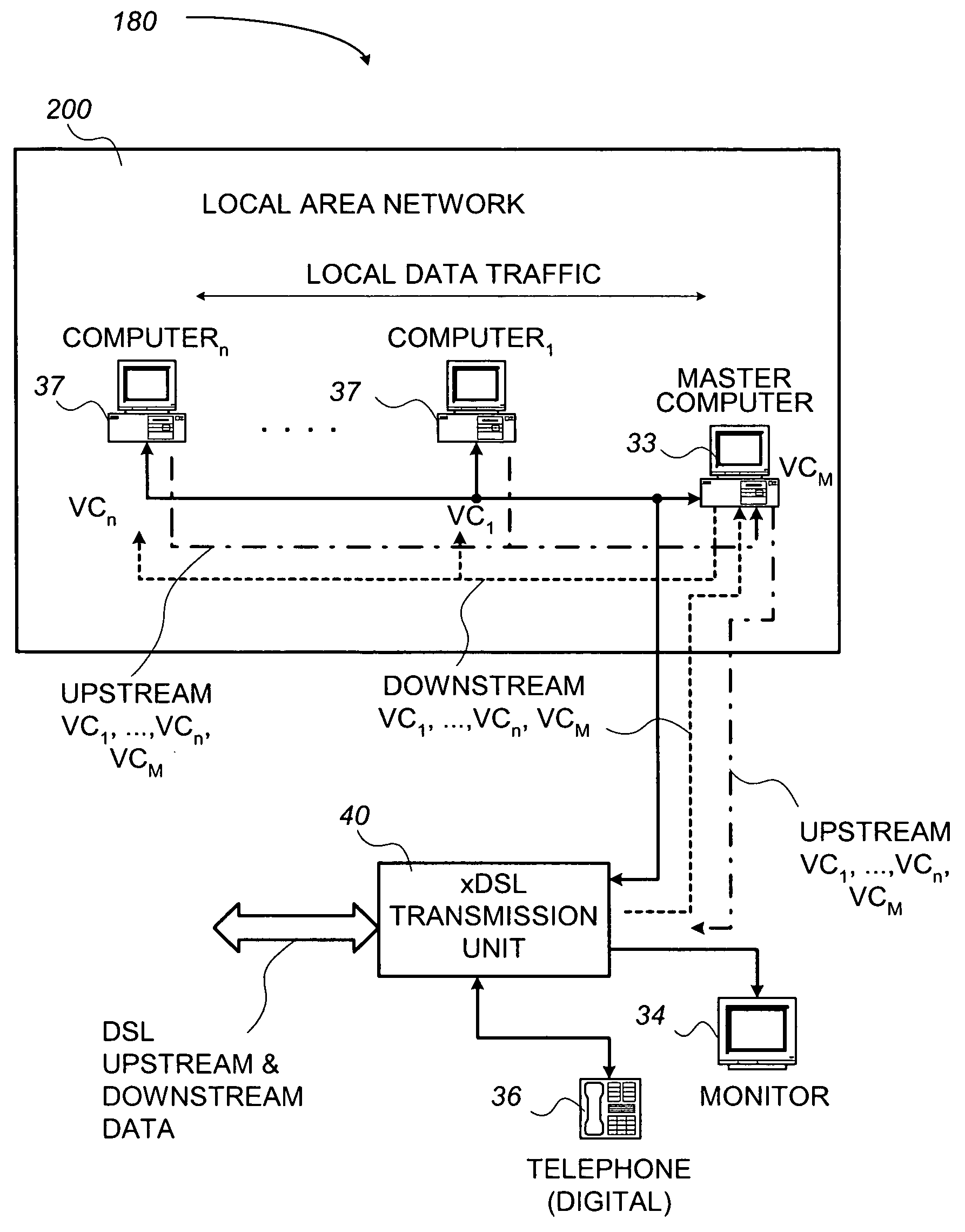
[0081]Having described the ATM cell format as illustrated in FIG. 5B and briefly introduced how a master computer on a LAN can be configured to enable a LAN to WAN interface, reference is now directed to FIG. 6. In this regard, FIG. 6 illustrates a point to multi-point DSL communication system consistent with the teachings of the present invention. A point to multi-point DSL communication system 180 in accordance with the present invention can be implemented in hardware, software, firmware, or a combination thereof. In preferred embodiment(s), the point to multi-point DSL communication system 180 may be implemented in software or firmware that is stored in a memory and that is executed by a suitable instruction execution system. If implemented in hardware, as in an alternative embodiment, the point to multi-point DSL communication system 180 can be implemented with any or a combination of the following technologies, which are well known and appreciated by those skilled in the art: a...

second embodiment

[0092]Having described a point to multi-point DSL communication system 180′ as illustrated in FIG. 7, reference is now directed to FIG. 8. In this regard, FIG. 8 illustrates a flowchart describing a method for establishing a point to multi-point DSL communication system 180 that may be implemented by the embodiment of FIG. 6.

[0093]It is important to note that any process descriptions or blocks in flow charts should be understood as representing modules, segments, or portions of code which include one or more executable instructions for implementing specific logical functions or steps in the process, and alternate implementations are included within the scope of the preferred embodiment of the present invention in which functions may be executed out of order from that shown or discussed, including substantially concurrently or in reverse order, depending on the functionality involved, as would be understood by those reasonably skilled in the art of the present invention.

[0094]As illu...


PUM


Abstract

A system that provides a multi-drop local area network (LAN) data transfer with devices on a wide area network (WAN) via a communication network is disclosed. Two methods for managing data traffic flow between individual nodes on a LAN and a WAN are also disclosed. The point to multi-point communication system may be implemented with a digital subscriber line (DSL) transceiver and compatibly configured communication devices coupled with each node or computer on a LAN. In one embodiment, the system uses a master computer on the LAN to manage protocol stacks to control the flow of downstream and upstream data traffic between computers on the LAN and WAN data traffic on a DSL. In a second embodiment, the master computer assigns at least one asynchronous transfer mode (ATM) level virtual connection (VC) to each computer on the LAN. Each computer on the LAN identifies data traffic designated to be sent to that particular computer, removes the data from the network, and notifies the master computer that the data traffic has been received. In the second embodiment, upstream data traffic is forwarded to the master computer, which maps the appropriate ATM VC identifier before forwarding the data to the DSL transceiver for transmission. Further alternative embodiments can use a community access television (CATV) network and a wireless network to bridge the LAN and the WAN.

Description

CROSS-REFERENCE TO RELATED APPLICATIONS[0001]The present application claims the benefit of U.S. Provisional Patent Application, assigned Ser. No. 60 / 135,987, filed May 25, 1999, now abandoned, entitled, “VC Spoofing,” which is hereby incorporated by reference in its entirety.BACKGROUND OF THE INVENTION[0002]1. Field of the Invention[0003]The present invention generally relates to high speed data communications wherein signal information is processed both in digital and analog forms. More specifically, the invention relates to a system and method that uses a single digital subscriber line (DSL) transmission unit within an end office of the public switched telephone network (PSTN) to establish high speed communication links with multiple users in a multi-drop network.[0004]2. Discussion of the Related Art[0005]In recent years, telephone communication systems have expanded from traditional plain old telephone system (POTS) communications to include high-speed data communications as wel...

Claims


Application Information

Patent Timeline
IPC IPC(8): G06F15/16
CPCH04L12/2801H04L12/2856H04L12/2889H04L12/2859H04L12/4625
Inventor BELL, RUSSELL W.
Owner SYNAPTICS INC
Why Eureka
Try Eureka