
Recording method and apparatus with an intermediate transfer medium based on transfer-type recording mechanism

a recording mechanism and transfer medium technology, applied in the direction of ink transfer from master sheet, duplication/marking method, printing, etc., can solve the problems of inaccurate image, deterioration of printing resolution, degraded printed image which is not dried fully, etc., to suppress ink liquid blur, excellent sharpness and light resistance, the effect of high quality

Inactive Publication Date: 2006-07-04
RICOH KK
View PDF38 Cites 35 Cited by
  • Summary
  • Abstract
  • Description
  • Claims
  • Application Information

AI Technical Summary

Benefits of technology

This approach results in high-quality images with improved light and water resistance, reduced ink liquid blur, and enhanced transfer efficiency, suitable for high-speed and energy-efficient printing without image blurring or color mixing issues.

Problems solved by technology

However, printing quality problems associated with producing images directly on a recording medium using ink jet technology include variations in printing conditions and quality depending on a type of a recording medium, such as an overhead projector sheet, a synthetic paper, an ink jet-dedicated paper or other recording media.
In addition, when printing on plain paper with a typical water-soluble ink, deterioration of printing resolution occurs because of ink liquid blur and ink liquid penetration problems (i.e., the ink liquid penetrates through the plain paper to a back surface of the plain paper) due to ink liquid migration through paper fibers.
Further, there is another problem that a printed image which is not dried fully is degraded when the recorded medium is ejected from a recording apparatus.
However, when an ink liquid is printed on the transfer medium, the ink liquid spreads inadequately, flows and mixes when producing a multicolor image, thereby producing an inaccurate image.
This method has an advantageous affect that a vivid image can be obtained, but is not applicable to a high-speed recording, energy-saving and high-resolution recording system because frequently, thermal energies and devices are required for generating the condensed ink on the transfer medium.
Like Japanese Laid-Open Patent Application No. 62-92849, the above two methods are not suitable for high-speed printing, the energy-saving and the high resolution printing system as well as a compact and a light apparatus, because of the same reasons described with respect to Japanese Laid-Open Patent Application No 62-92849.
In other words, there is a disadvantage in that it is difficult to obtain a high resolution image with good sharpness because an overall dimension of the ink liquid is likely to spread on the layer coated by the surfactant in comparison with an ink liquid size ejected from a recording head.
Moreover, since the ink liquid is transferred to a recording medium together with the surface active agent, an additional disadvantage is that ink liquid bleeding occurs due to co-penetration of the ink liquid and the surface active agent into the recording medium, such as a paper.
Because transfer based on this type is carried out at temperature of from about 200° C. to about 300° C. as a softening temperature of a separating layer, there is provided a problem of d high-speed recording and system reliability.
On the other hand, this method has a drawback in that, because of ion-exchangeable modification of a dye composition in the ink liquid with the ion-exchange resin layer, a color tone of the ink on the recording medium is changed subtly.
Because a concentration of the ink liquid remains constant, the ink is transferred to the recording medium, thereby producing a problem that a transferred image experiences ink liquid blurring, penetration problems and color mixing.
In addition, since an ammonia gas is generated upon heating the ion-exchange resin layer for reuse, there is provided a pollution problem.
Additionally, this method does not meet the requirement for a high-speed printing, low energy consumption, high resolution printing, compact and light system with maintenance-free operation due to deterioration and reuse and the like for the ion-exchange resin layer.
However, this has a problem that there are required a dedicated cleaning members, such as a blade and a brush or the like for cleaning the unused powder remaining on the intermediate transfer medium after transfer to the recording medium.
In general, since an area of a background portion of the intermediate transfer medium is larger than that of an imaged part, a quantity of the powder for use in this type tends to become large.
Additionally, when the powder in an unused state is allowed to stand for a long time, the powder on the intermediate transfer medium absorbs water to cause viscosity of the powder to be increased, thereby leading to occurrence of a problem that the powder having water absorbed can not be cleaned by the cleaning member.
Moreover, properties such as water resistance and light resistance for a dye-based ink liquid is usually inferior to that for a pigment-based ink liquid, although images formed by the former have high chroma and vivid color tones.
However, this ink liquid causes a clogged recording head problem and another disadvantage in that ejection stability is unsatisfactory for the ink jet recording method in which the ink droplet is ejected.
The foregoing patents solve some problems associated with the ink jet recording which produces images on the recording medium, but the major problems of image feathering, color to color blur and liquid penetration have not been solved.

Method used


Image

  • Recording method and apparatus with an intermediate transfer medium based on transfer-type recording mechanism
  • Recording method and apparatus with an intermediate transfer medium based on transfer-type recording mechanism
  • Recording method and apparatus with an intermediate transfer medium based on transfer-type recording mechanism

Examples


example 1

[0073]The experimental conditions were as follows:

Liquid Recording Device:

[0074]An ink-jet printer based on an intermediate transfer mechanism, having a recording head for projecting a liquid in response to an image signal, was used in this experiment.

Recording Medium:

[0075]Wood-free paper (Ricoh PPC paper).

Intermediate Transfer Element:

[0076]There was used a mixture of poly(acrylic acid)(Hitachi Chemical, this material will be hereinafter abbreviated to PAA) which has water-absorbing ability as a thickener member and SUMISOPU 90(Sumitomo Chemical) as the ultraviolet stabilizer.

Method for Forming an Image to the Recording Medium:

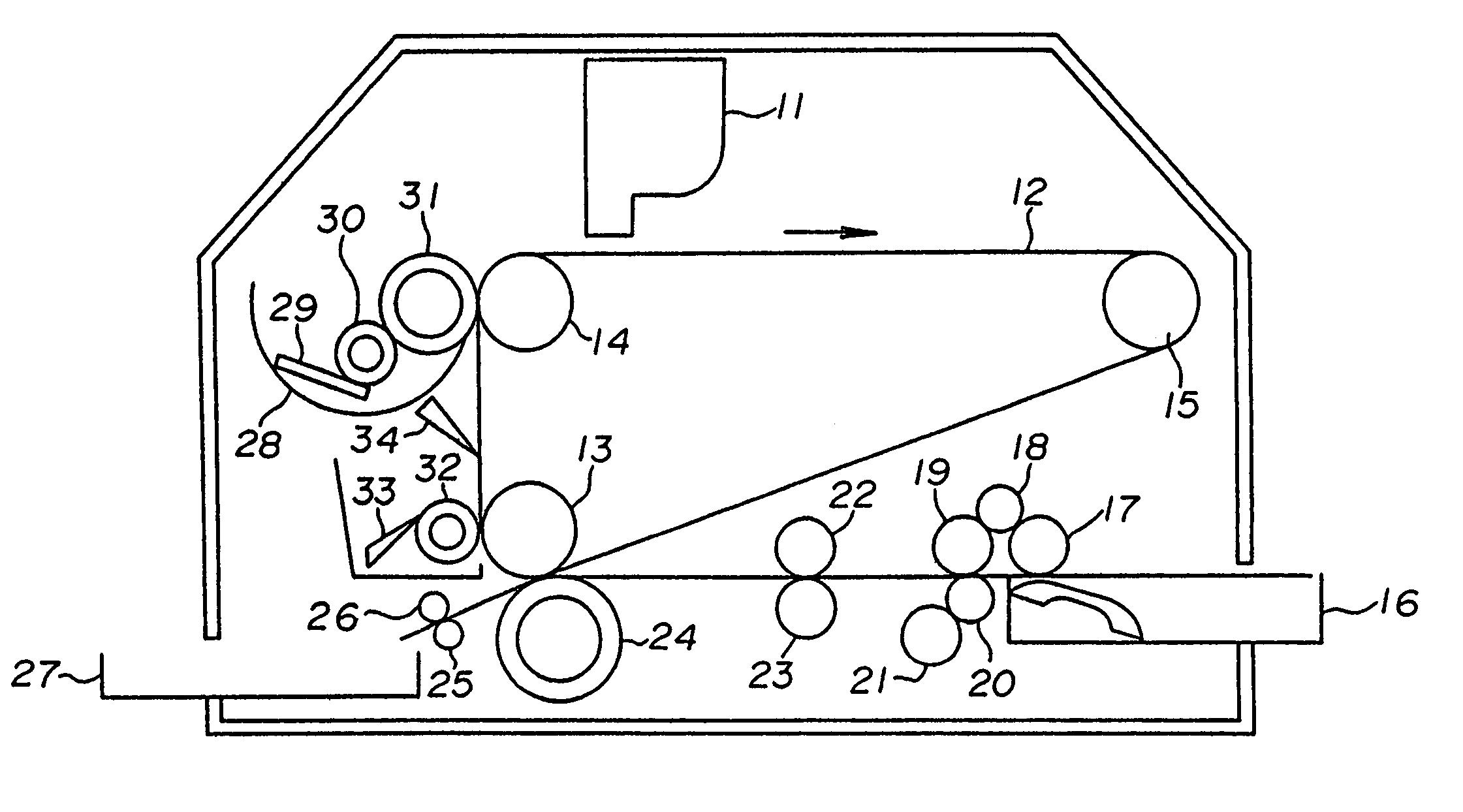
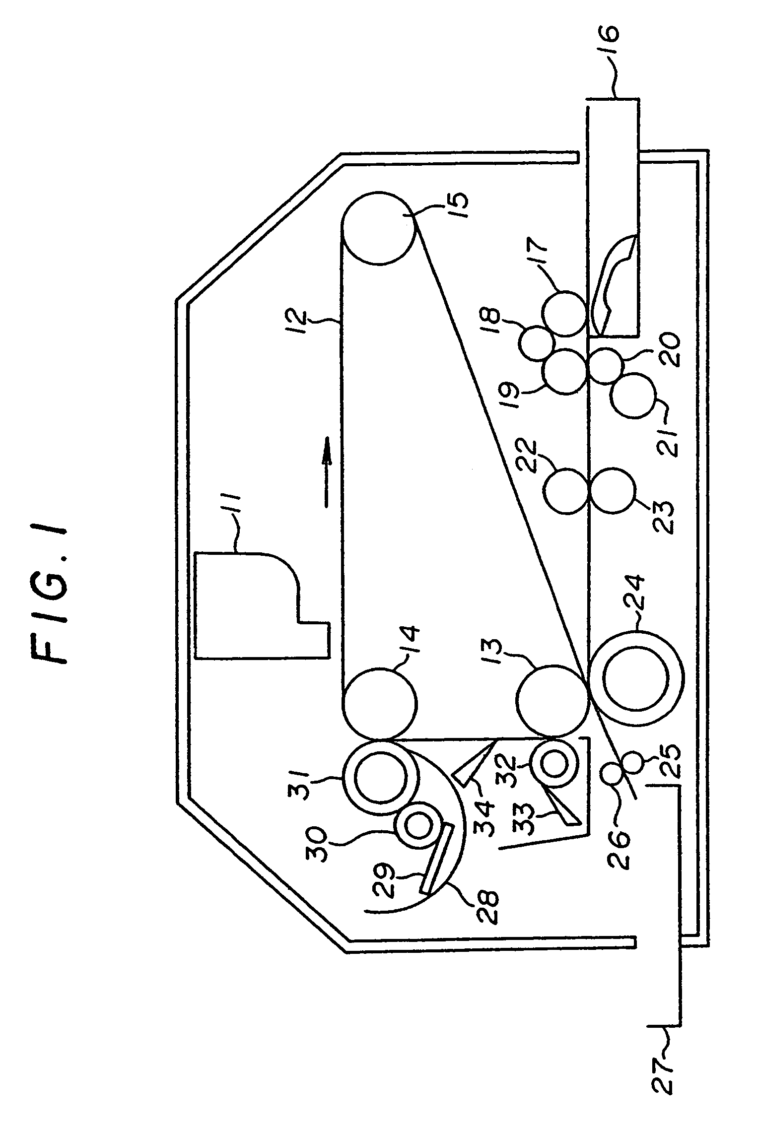
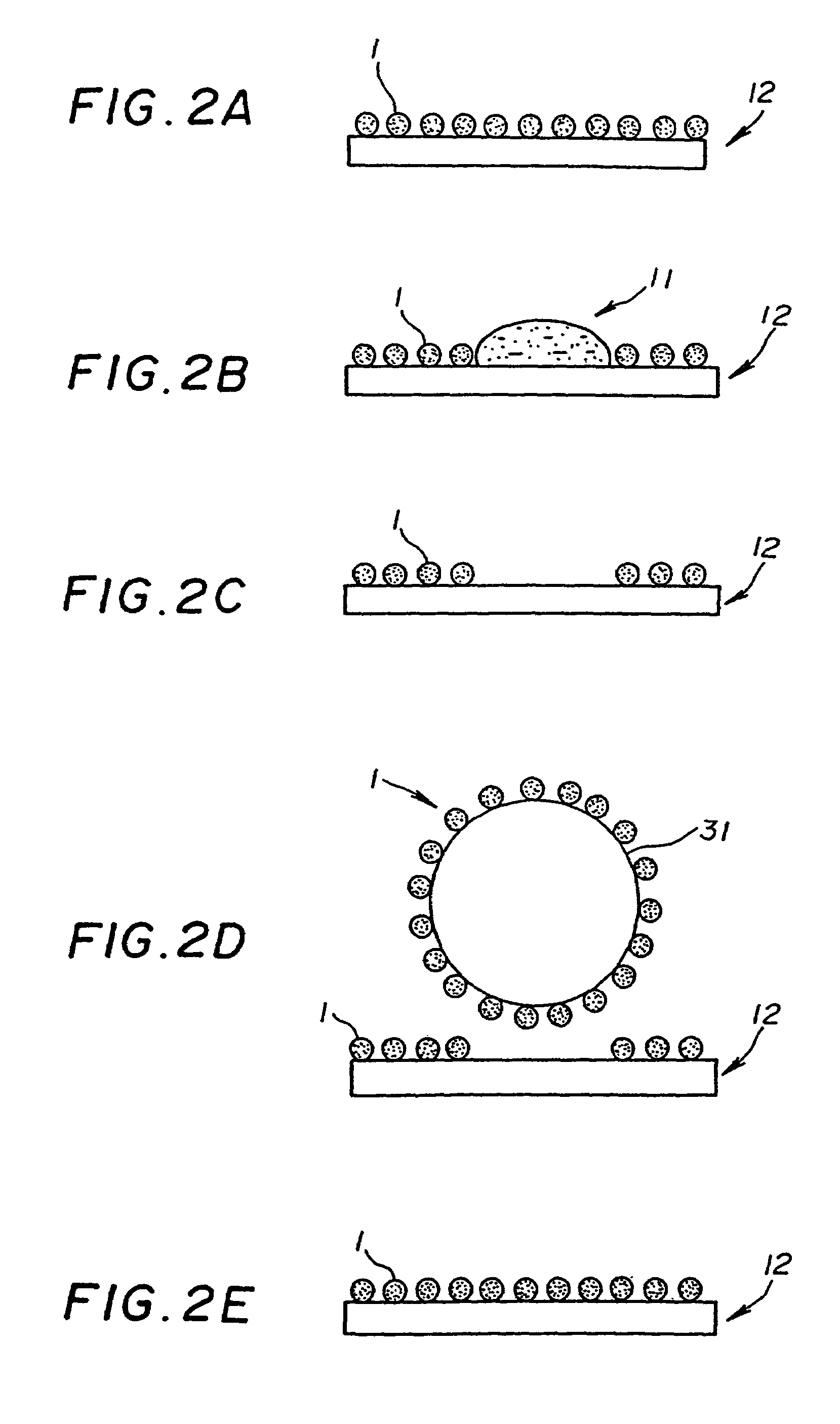
[0077]As is shown in FIG. 1, the above ITE including the above mixture was coated on the ITM which is a water-repellent member. By using the liquid recording device, images were produced on the wood-free paper, comparing with images printed by means of a conventional method which does not use an intermediate transfer-type recording mechanism.

Evaluation of Li...

example 2

Liquid Recording Device:

[0080]The same device as EXAMPLE 1 was used.

Recording Medium:

[0081]Wood-free paper (Ricoh PPC paper).

Intermediate Transfer Element:

[0082]A mixture of PAA and 1 wt % of the ultraviolet stabilizer, DIC-TBS (Dainippon Ink Chemicals), relative to PAA, was used.

Method for Forming an Image to the Recording Medium:

[0083]As is shown in FIG. 1, the above ITE including the above mixture was coated on the ITM which is a silicone rubber. By using the same liquid recording device as EXAMPLE 1, images were produced on the wood-free paper.

Evaluation of Light Resistance:

[0084]Evaluation was carried out in the same way as EXAMPLE 1.

Results:

[0085]In comparison with images produced by the ink jet printing based on the conventional method, good images having water resistance were formed while eliminating ink liquid blurring and liquid penetration problems. After irradiation as explained in EXAMPLE 1, a residual OD value of the images transferred from the ITE containing the ultra...

example 3

Liquid Recording Device:

[0086]The same device as EXAMPLE 1 was used.

Recording Medium:

[0087]Wood-free paper (Ricoh PPC paper).

Intermediate Transfer Element:

[0088]A mixture of PAA and 1 wt % of the ultraviolet stabilizer, cerium oxide (Nidoraru (Taki Chemicals)), relative to PAA, was used.

Method for Forming an Image to the Recording Medium:

[0089]As is shown in FIG. 1, the above ITE including the above mixture was coated on the ITM which is a silicone rubber. By using the same liquid recording device as EXAMPLE 1, images were produced on the wood-free paper.

Evaluation of Light Resistance:

[0090]Evaluation was carried out in the same way as EXAMPLE 1.

Results:

[0091]In comparison with images produced by the ink jet printing based on the conventional method, good images with water resistance were formed while eliminating ink liquid blur and liquid penetration problems. After irradiation, a residual OD value of the printed images transferred from the ITE containing the ultraviolet stabilizer...


PUM

PropertyMeasurementUnit
softening temperatureaaaaaaaaaa
particle diameteraaaaaaaaaa

Abstract

An apparatus and method for recording an image using a transfer-type recording mechanism are such that a layer of an intermediate transfer element is removably formed on a surface of an intermediate transfer medium. The intermediate transfer element includes an ultraviolet stabilizer and a powder mixture. The intermediate transfer layer is capable of being dissolved and swelled by applying an ink liquid on the intermediate transfer medium and enables a viscosity of the ink liquid residing thereon to be increased. An image is produced on the intermediate transfer medium by supplying the ink liquid thereon. The image is then transferred to the recording medium, so that a high quality image is produced without any blurring, mixing or penetration of the ink liquid.

Description

CROSS-REFERENCE TO RELATED APPLICATIONS[0001]This is a divisional application of U.S. application Ser. No. 10 / 648,111 filed Aug. 26, 2003 now U.S. Pat. No. 6,837,578, the disclosure of which is hereby fully incorporated by reference and which is a divisional application of U.S. application Ser. No. 09 / 442,869 filed Nov. 18, 1999, now U.S. Pat. No. 6,623,816 B1, the disclosure of which is hereby fully incorporated by reference.BACKGROUND OF THE INVENTION[0002]The present invention generally relates to a recording method and apparatus using a liquid printing device. More particularly, the present invention is directed to a transfer-type recording mechanism in which a liquid printing device prints a recording liquid on a layer of an intermediate transfer element provided on an intermediate transfer medium in response to an imaging signal to form an image on the layer of the intermediate transfer element, and then the image is transferred to a recording medium.[0003]A recording method u...

Claims


Application Information

Patent Timeline
Patent Type & Authority Patents(United States)
IPC IPC(8): B41J2/01B41J2/005B41M5/025B41M5/035B41M5/382
CPCB41J2/0057B41M5/0256B41M5/38257B41M5/0355
Inventor TANIKAWA, KIYOSHISAITO, TADASHINOGUCHI, AINOKATANO, YASUOMURAKAMI, KAKUJIHASEBE, MITSUOKAWAKUBO, TOSHIOTOMITA, SATORUTAKAHASHI, TOMOKOYANAGAWA, NOBUYUKI
Owner RICOH KK
Learn More