Composite with a low emissivity in the medium and far infrared, and with a low reflectivity in the visible and near infrared

a technology of composite, which is applied in the field of composite with a low emissivity in the medium and far infrared, and with a low reflectivity in the visible and near infrared, can solve the problems of degrading the properties of varnishes, frequently reapplied, and unsatisfactory use of varnishes

Inactive Publication Date: 2006-07-04
ALENIA AERONAUTICA SPA +1
View PDF4 Cites 0 Cited by
  • Summary
  • Abstract
  • Description
  • Claims
  • Application Information

AI Technical Summary

Benefits of technology

[0009]The invention's multi-layer composite product is capable of reducing mid- and far-infrared emissivity (between 2.5 and 4 μm and between 8 and 14 μm), by providing an average value lower than 0.4, while maintaining a low reflexivity in the visible band (neutral or grey coloration) and in the near-infrared (between 0.7 and 2.5 μm), by providing an average value lower than 0.3.

Problems solved by technology

However, the employment of such varnishes is considered not entirely satisfactory.
Such varnishes, in fact, when exposed to their normal operating conditions, tend to rapidly deteriorate and erode, thus, rapidly degrading their properties, so that they have to be frequently reapplied.

Method used


Image

  • Composite with a low emissivity in the medium and far infrared, and with a low reflectivity in the visible and near infrared
  • Composite with a low emissivity in the medium and far infrared, and with a low reflectivity in the visible and near infrared
  • Composite with a low emissivity in the medium and far infrared, and with a low reflectivity in the visible and near infrared

Examples


example 1

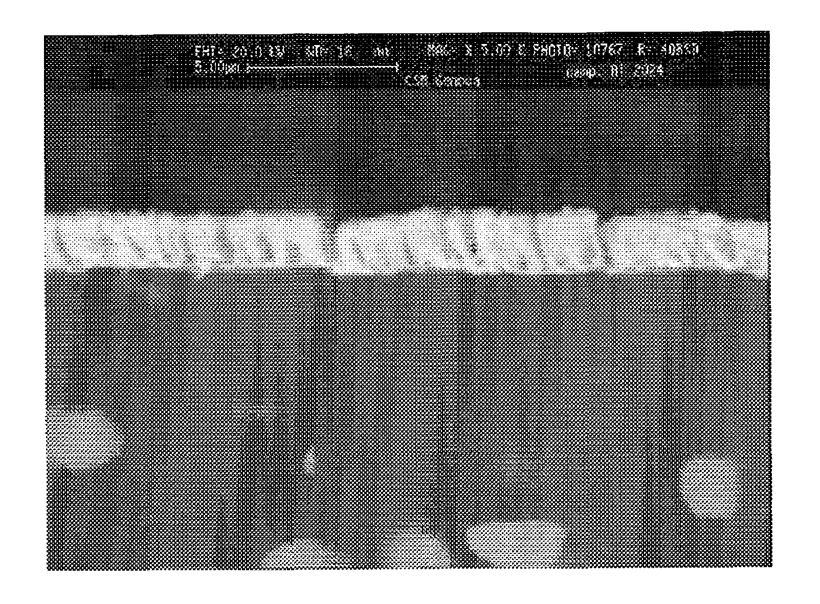
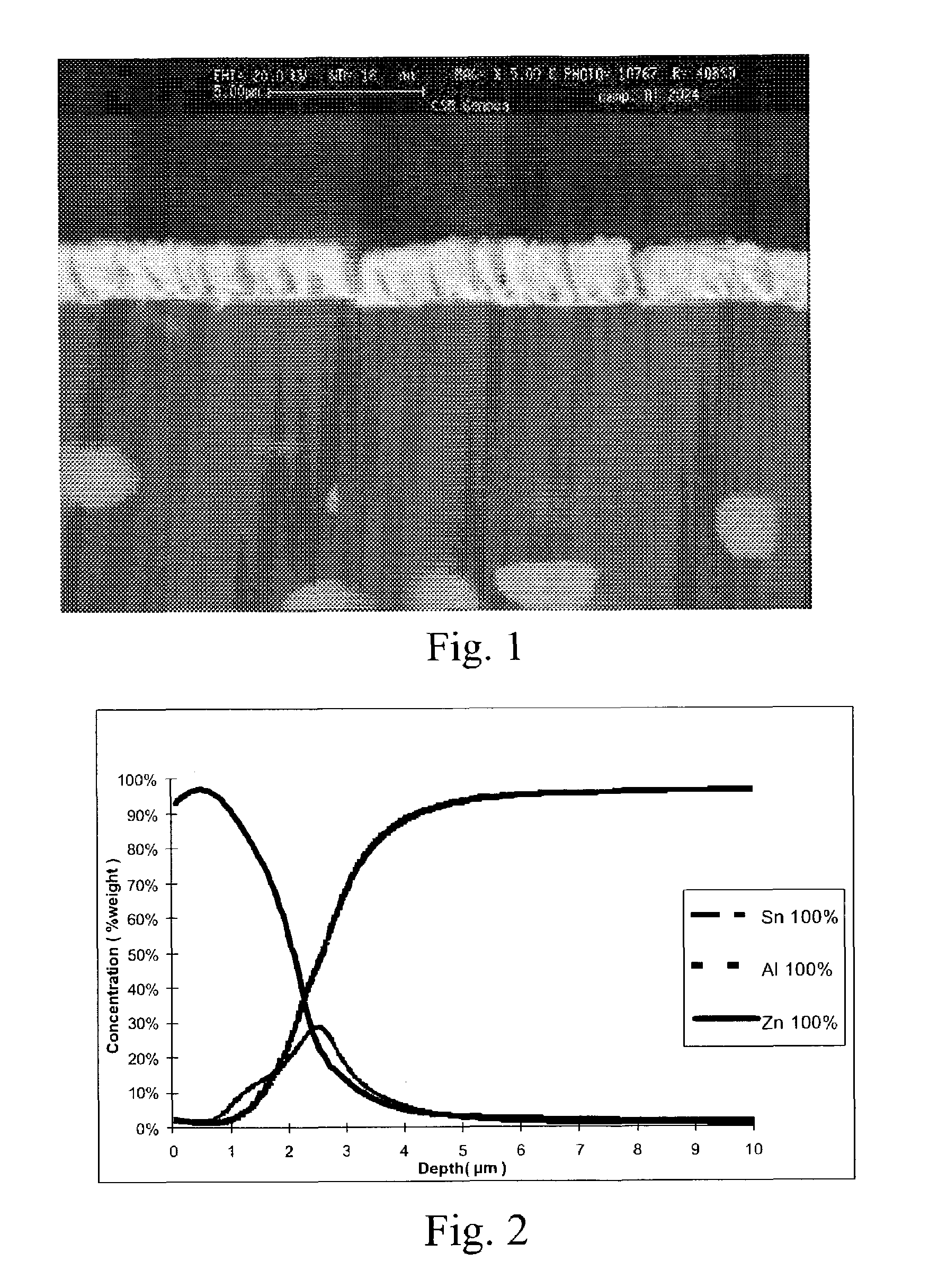
(Aluminum-Alloy-Based Product, with Zinc Oxide Coating, Doped with Aluminum (AZO) and an Intermediate Layer of Tin).

[0042]The product was obtained using a procedure that will be described in detail below, by employing the evaporation PVD technology. Such procedure was optimised considering three general conditions:[0043]Decrease in thickness, with the goal of diminishing the residual stresses;[0044]Deposition of the various layers without opening the deposition chamber;[0045]Process temperature kept well below 150° C. to prevent degradation of the mechanical properties of the base material.

[0046]The product was obtained using PVD evaporation technology as follows:[0047]Chemical cleaning of the base material[0048]Ion bombardment[0049]Deposition of three subsequent substrates of tin, zinc and aluminum in sequence, by keeping the chamber at low pressure; an electrical resistance evaporator was used for the zinc, while the tin and aluminum were evaporated using an EB (Electron Beam) ele...

example 2

(Aluminum-alloy-based Product, with Zinc Oxide Coating, Doped with Aluminum (AZO))

[0060]The product was obtained using a procedure that will be described in details below, employing the evaporation PVD technology. In this example as well, such procedure was optimised considering the three general conditions described in Example 1.

[0061]The product was obtained using the PVD evaporation technology as follows:[0062]Chemical cleaning of the base material[0063]Ion bombardment[0064]Deposition of a layer of zinc and aluminum; evaporated by using an electronic gun.

[0065]Table I shows the process parameters used for the deposition of the product described above, by alternating the beam's action on the two crucibles containing zinc and aluminum, so that a layer of a 97%-zinc-and-3%-aluminum alloy may be deposited.

[0066]Table III shows the process parameters used for the deposition of the product described above.

[0067]

TABLE IIIIon bombardmentDepositionTemper-Temper-CoatingTimeatureTimeatureEB...

example 3

(Aluminum-alloy-based Product, with Indium-oxide-based Coating, Doped with Tin (ITO) and Intermediate Layer of Tungsten Oxide)

[0074]The product was obtained as follows:[0075]Deposition, by using PVD sputtering, of a Tungsten Oxide layer (WO3);[0076]Deposition, by using PVD sputtering, of an Indium Oxide layer, doped with 10% of Tin (ITO).

[0077]Table V shows the process parameters used for the deposition of the two layers.

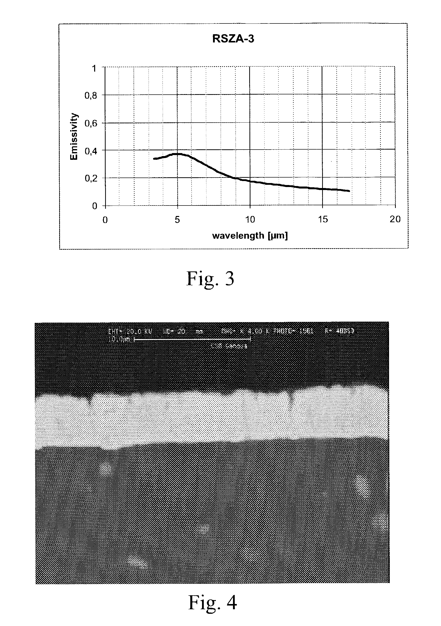
[0078]The attached FIG. 6FIG. 6 shows the emissivity in the infrared of the product shown in this example: the sample shows an average value lower than 0.2 in the mid- and far-infrared.

[0079]

TABLE VPotentialBiasDeposition TimeMaterial(V)(V)(minutes)WO36005.545ITO5505.520

[0080]To determine the optical properties in the visible and near-infrared, reflexivity measurements were taken on the product, the results of which are shown in the attached FIG. 7: the sample shows an average value lower than 0.2 in the visible and lower than 0.3 in the near infrared.


PUM

PropertyMeasurementUnit
wavelengthaaaaaaaaaa
emissivityaaaaaaaaaa
thickaaaaaaaaaa

Abstract

Multi-layer composite product, featuring low emissivity in the mid-infrared band (as wavelength range 2,5–5 μm) and far-infrared (as wavelength range 8.0–14.0 μm) bands, as well as low reflexivity in the near-infrared (at a wavelength range of 0.7–2.5 μm) and in the visible (as wavelength range 0.3–0.7 μm) bands, including a base constructed with low-density and / or high thermal-resilience structural materials, covered with optionally doped coating, and where, between the base and the coating, at least one intermediate layer of metals or metal oxides is planned for insertion.

Description

BACKGROUND OF THE INVENTION[0001]1. Field of Invention[0002]This invention refers to products intended for the aeronautical industry featuring low infrared emissivity and low visible light reflexivity.[0003]2. Description of the Prior Art[0004]As it is generally known, with regard to coated products, the coating in question must have a high degree of adhesiveness and must withstand transitory mechanical and thermal stresses, which may cause its detachment.[0005]A commonly employed solution relies upon the use of special varnishes containing particles of materials featuring the desired optical characteristics. However, the employment of such varnishes is considered not entirely satisfactory. Such varnishes, in fact, when exposed to their normal operating conditions, tend to rapidly deteriorate and erode, thus, rapidly degrading their properties, so that they have to be frequently reapplied. An example of coating of the above-mentioned type is described in the American patent U.S. Pat...

Claims


Application Information

Patent Timeline
Patent Type & Authority Patents(United States)
IPC IPC(8): B32B9/04C23C14/02C23C14/08
CPCC23C14/0015C23C14/024C23C14/086C23C14/08Y10T428/30Y02T50/60
Inventor TULUI, MARIOVALLE, ROBERTAMORTONI, FLAVIOPROTTI, MARCO
Owner ALENIA AERONAUTICA SPA
Why Eureka
Try Eureka