High efficiency brake for agricultural drive systems

a technology of agricultural drive system and high efficiency brake, which is applied in the direction of braking system, transportation and packaging, etc., can solve the problems of damage to the drivetrain and the irrigation equipment itself, machine fatigue, and uncontrollable downhill rolling of machinery, etc., and achieve high efficiency, rusting and other corrosion problems, and high efficiency.

Inactive Publication Date: 2006-07-11
DANIEL JEFFREY K
View PDF7 Cites 17 Cited by
  • Summary
  • Abstract
  • Description
  • Claims
  • Application Information

AI Technical Summary

Benefits of technology

[0012]These and other objects are achieved through the high efficiency drivetrain of the present invention. The drivetrain includes a ball ramp brake to inhibit movement of the wheel tower when the drive gear motor is not driving. In one embodiment, the ball ramp brake is bi-directional. More specifically, the drivetrain comprises a bi-directional ball ramp brake disposed between the drive gear motor and the divider gearbox of the drivetrain. Utilizing a ball ramp brake such as this, the divider gearbox can incorporate much more highly efficient gearing mechanisms, such as for example only, involute gears, beveled gears, planetary gears or the like. The ball ramp brake is enclosed and includes an oil bath that functions to lubricate the components of the brake. Since the brake is enclosed and operates in a wet environment, i.e., the lubricant contained in the brake enclosure surrounds the brake, rusting and other corrosion problems experienced in the prior art are minimized. An additional benefit to such a brake is that the lubricant also dissipates heat generated by the brake, yielding a longer operational life. In one embodiment of the invention, the brake is enclosed within the divider gearbox housing.

Problems solved by technology

To the extent such equipment is positioned on an incline, there is a concern that the machinery could roll uncontrolled down the incline as the output shaft “back drives”, i.e., rolling backwards down a hill, or “forward drives”, i.e., rolling forwards down a hill, the gearing.
Such uncontrolled motion can result in damage to the drivetrain and the irrigation equipment itself.
However, one drawback to standard worm gearsets is that they typically have efficiencies of only about 50%.
Because worm gears are a friction gear mesh, the friction between the worm gear set results in elevated heat and loss of power, thereby decreasing efficiency.
However, the extreme weather conditions of cold, heat and precipitation often result in a buildup of condensation within even an enclosed case.
Because of this environment, the brake components have a tendency to rust.
This becomes a particular problem when the machinery has been idle for a period of time, such as during the winter season.
In such cases, the brake components often rust bond together, rendering the brake inoperable.
In addition to any resultant rusting to the brake components, this moisture can cause malfunction of the electrical components of the brake.
Thus, such electromechanical brakes have been found to be undesirable for use in the drivetrain of agricultural irrigation equipment.

Method used


Image

  • High efficiency brake for agricultural drive systems
  • High efficiency brake for agricultural drive systems
  • High efficiency brake for agricultural drive systems

Examples


Embodiment Construction

[0018]In the detailed description of the invention, like numerals are employed to designate like parts throughout. Various items of equipment, such as fasteners, fittings, etc., may be omitted to simplify the description. However, those skilled in the art will realize that such conventional equipment can be employed as desired.

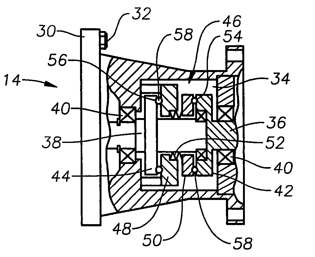
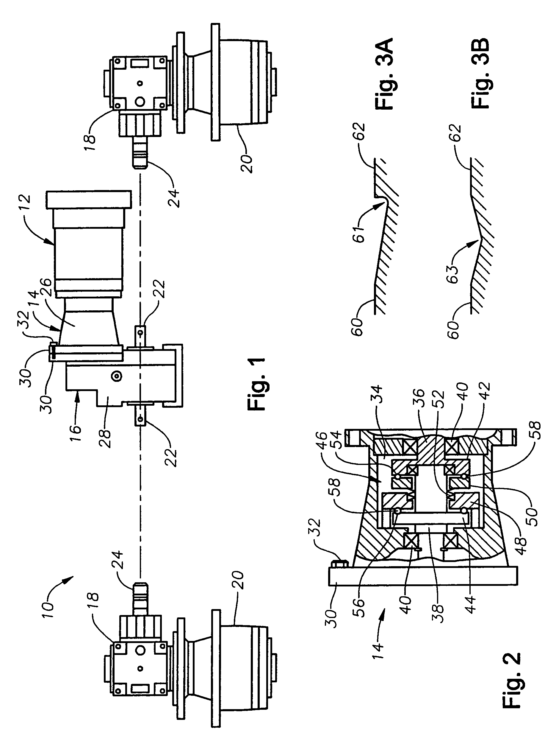
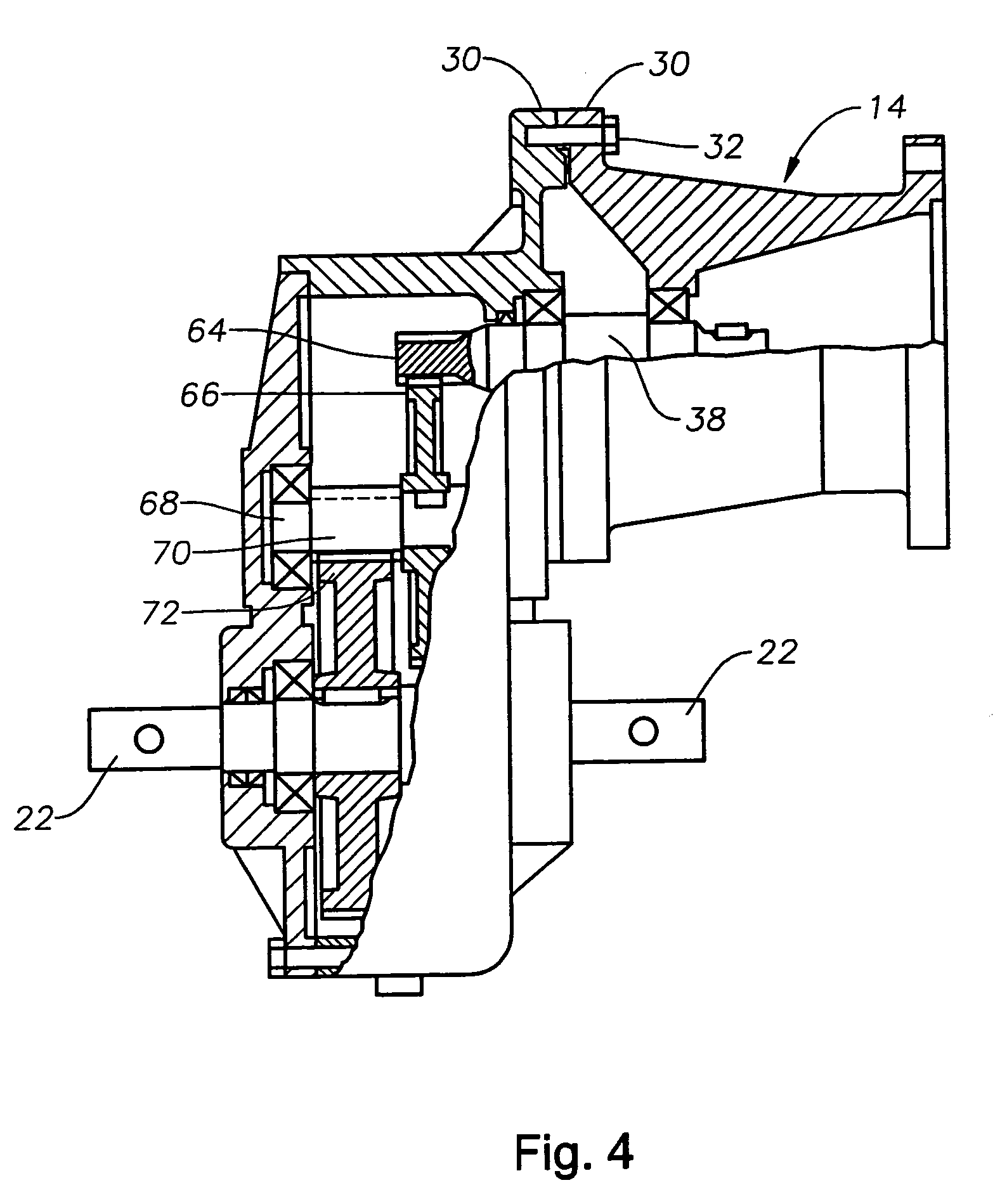
[0019]With reference to FIG. 1, an agricultural irrigation system drivetrain 10 is illustrated. Drivetrain 10 generally comprises a drive gear motor 12, a ball ramp brake 14, a divider gearbox 16, a wheel drive gearbox 18 and a wheel hub 20. Ball ramp brake 14 is disposed between drive gear motor 12 and divider gearbox 16. An output shaft 22 from divider gearbox 16 is coupled to the input shaft 24 of wheel drive gearbox 18 by a drive shaft 26.

[0020]In the embodiment illustrated in FIG. 1, the enclosures for brake 14 and divider gearbox 16 are separate. Specifically, ball ramp brake 14 includes enclosure 26 while divider gearbox 16 includes enclosure 28. Althou...


PUM


Abstract

A high efficiency drivetrain for an agricultural irrigation system is described. The drivetrain includes a ball ramp brake to inhibit movement of a wheel tower when the drive gear motor is not engaged. In one embodiment, the ball ramp brake is a bi-directional ball ramp brake disposed between the drive gear motor and the gearbox of the drivetrain. Utilizing a ball ramp brake such as this, the gearbox can incorporate much more highly efficient gearing mechanisms, such as for example only, involute gears, beveled gears, hypoid gears, planetary gears or the like. The ball ramp brake is enclosed and includes an oil bath that functions to lubricate the components of the brake, preventing corrosion and dissipating heat.

Description

BACKGROUND OF THE INVENTION[0001]1. Field of the Invention[0002]The present invention relates to the field of power transmission for use in mechanized agricultural equipment, and more particularly to a high efficiency drive train incorporating an internal brake to prevent freewheeling.[0003]2. Description of the Prior Art[0004]Center pivot and linear irrigation systems are well known in the art for their ability to irrigate large sections of land. Typically, such systems are capable of watering a quarter section of land, i.e., 160 acres, or more. A center pivot irrigation system generally comprises an elongated primary irrigation pipe that extends radially outward from a center pivot. When activated, the irrigation pipe rotates around the pivot, thereby watering the area that the irrigation system passes over and resulting in a circular pattern of water coverage about the central pivot point. The length of time involved in a 360 degree rotation of the irrigation pipe may be up to se...

Claims


Application Information

Patent Timeline
Patent Type & Authority Patents(United States)
IPC IPC(8): B60T7/12F16D67/00B60K17/04B60T1/06F16H1/20
CPCB60K17/04B60T1/062F16H1/20B60Y2200/224
Inventor DANIEL, JEFFREY K.
Owner DANIEL JEFFREY K
Why Eureka
Try Eureka