

Use of low pressure distillate as absorber oil in a FCC recovery section
a technology of low pressure distillate and recovery section, which is applied in the direction of gaseous mixture working up, effluent separation, separation process, etc., can solve the problems of unit operations forming bottlenecks, insufficient capacity primary absorber and/or stripper, etc., and achieves less equipment and increased the effect of main fractionator, compressor and stripper/absorber outpu
- Summary
- Abstract
- Description
- Claims
- Application Information
AI Technical Summary
Benefits of technology
Problems solved by technology
Method used
Image

Examples
Embodiment Construction
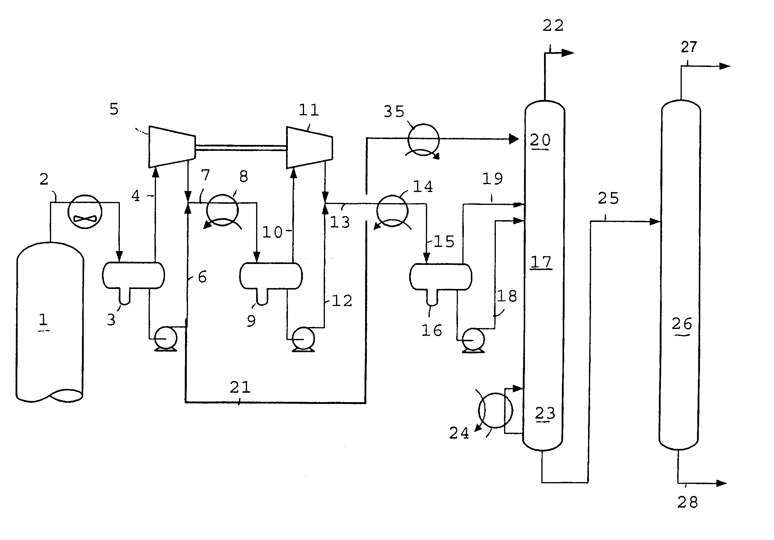
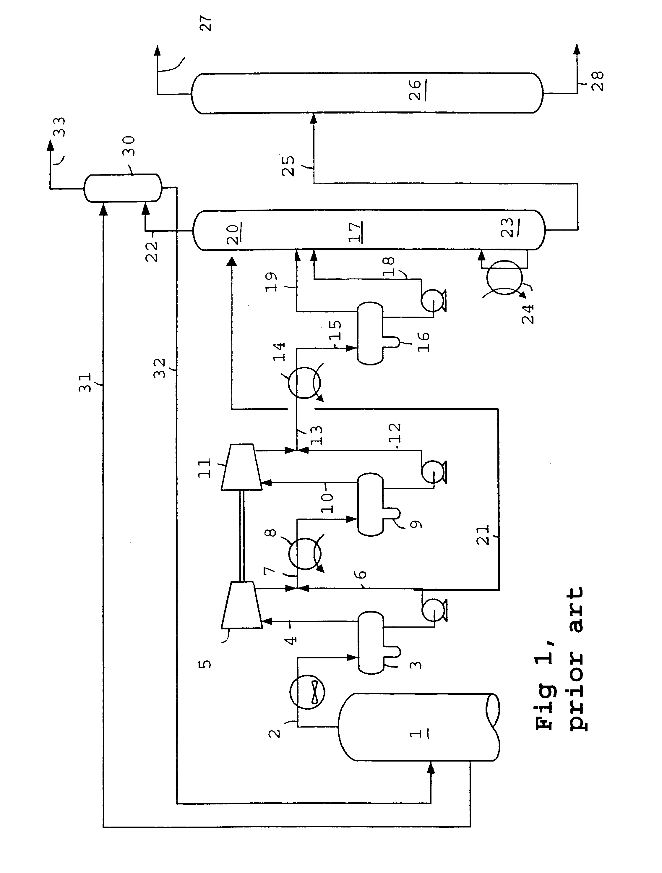
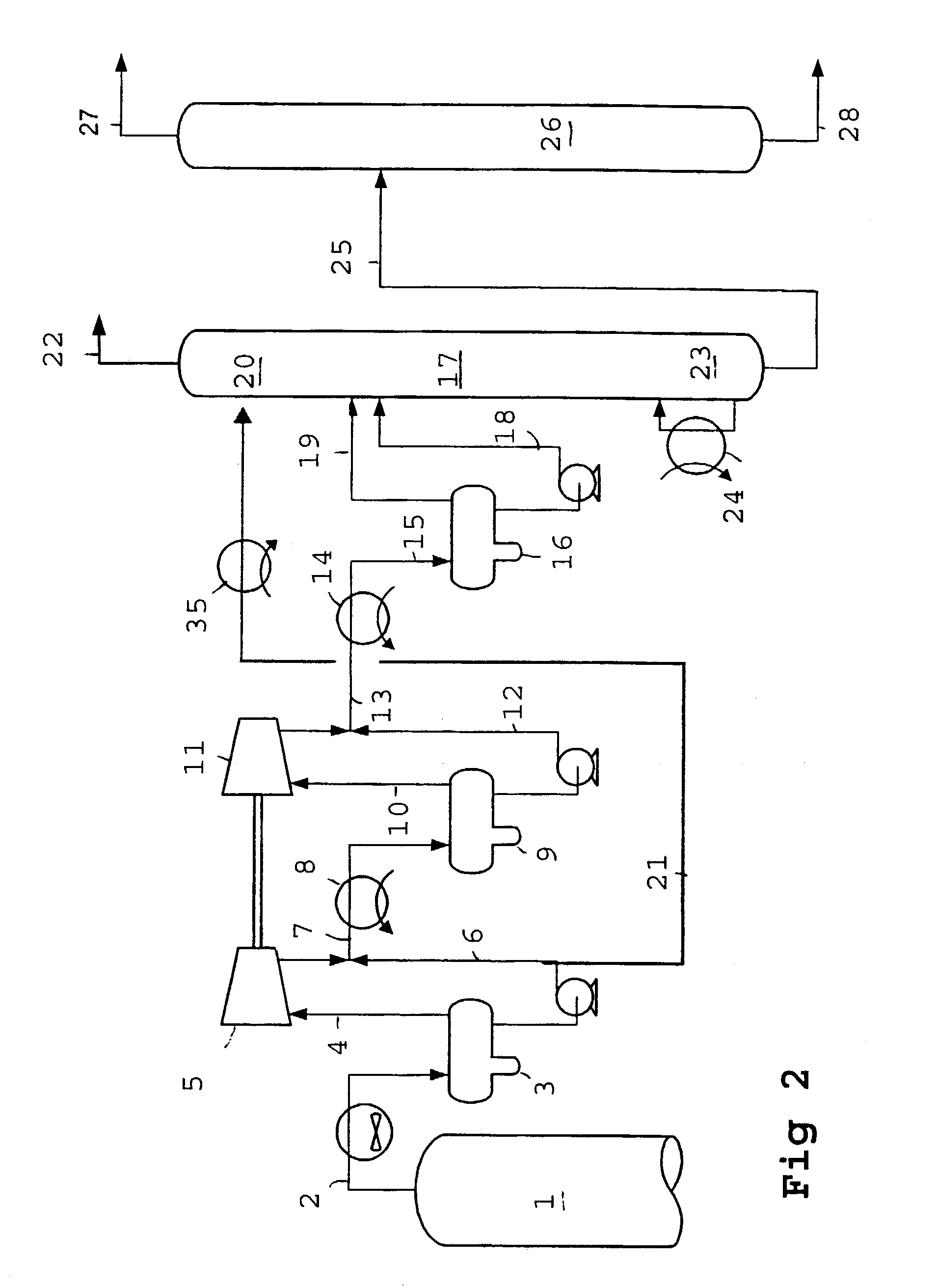
[0020]FIG. 1 illustrates a state of the art process for the recovery of gaseous products from the product mixture obtained by contacting a hydrocarbon feed with a catalyst in a fluid catalytic cracking process. FIG. 1 shows the top part of a first distillation column 1, also referred to as main fractionator, a gas conduit 2, a main fractionator overhead drum 3 from which a gas conduit 4 supplies a gaseous product to a first compressor step 5. Part or all of the liquid fraction obtained in separator 3 is supplied via conduit 21 to absorber section 20. The compressed gaseous fraction obtained in compressor 5 is optionally combined with the remaining part of the liquid fraction via 6 obtained in the overhead drum 3 in conduit 7 and cooled in heat exchanger 8. The cooled gas-liquid fraction is separated in liquid and gaseous fractions in separator 9. The gaseous fraction is supplied via 10 to a second compressor step 11. The liquid fraction via conduit 12 is combined with the compressed...
PUM
| Property | Measurement | Unit |
|---|---|---|
| temperature | aaaaa | aaaaa |
| temperature | aaaaa | aaaaa |
| boiling point | aaaaa | aaaaa |
Abstract
Description
Claims
Application Information