Method and apparatus for nanoparticle transport and detection

a technology of nanoparticles and nanoparticles, applied in the field of nanoparticles, can solve the problems of difficult to implement quantitative data analysis for such models, and difficult to ensure structural uniformity, etc., to achieve tight control over fabrication conditions, improve the detection accuracy of particle particles, and improve the effect of structure uniformity

Inactive Publication Date: 2006-07-18
TEXAS A&M UNIVERSITY
View PDF4 Cites 92 Cited by
  • Summary
  • Abstract
  • Description
  • Claims
  • Application Information

AI Technical Summary

Benefits of technology

[0011]Some embodiments of the present invention provide a number of technical advantages. For example, according to one embodiment of the present invention using a nanotube in combination with a membrane to produce a membrane having a single nanopore overcomes some of the disadvantages described above with previous single nanopore membranes. Membranes having a plurality of nanopores may also be produced in a similar fashion. Furthermore, some embodiments of the invention provide additional advantages. For example, the geometric and chemical properties of the resulting nanopore may be well-defined because of the characteristics of the nanotube. In particular, for a carbon nanotube, the pore diameter is usually uniform along the entire pore length and a set of nanoporous membranes of essentially identical diameter can be obtained if they are all derived from a common nanotube. This is a clear advantage over most lithographic methods in which very tight control over fabrication conditions is required to achieve identical replicates. Additionally, wall 14 of nanotube 10, in one embodiment, is an atomically smooth graphic sheet, which may be the best approximation of theoretical models that assumes a “structureless wall.” Good approximation of the critical models allows for more accurate particle detection when membrane 16 is used in particle detection. Additionally, a single nanotube embedded within a highly stable polymeric matrix, in one embodiment, constitutes a good configuration for reducing interference due to leakage and Faradic currents because the polymer matrix is normally a good insulator for both electron and ion conduction. Many such nanopore membranes can be prepared rapidly due to the efficiency of certain manufacturing approaches, some of which are described below. This greatly enhances reproducibility and reduces sample preparation time, making the approach practical for routine studies.

Problems solved by technology

Quantitative data analysis for such models is difficult to implement because a complete description of a polydisperse structure is almost impossible without invoking many approximations and assumptions.
First, it is difficult to ensure structural uniformity in arrays containing 10 or more pores (assuming a pore diameter of 100 nm and a sample area of 1 cm2); the problem is exacerbated as the pore dimensions become very small.
Second, under steady-state conditions, only a time-averaged transport rate can be determined because individual single-pore transport events cannot be temporally resolved from each other.
Thus, statistical distribution in transport rate cannot be retrieved using an array-pore membrane model.
However, these protein channels are dynamically complex structures and may not be good models for testing existing theories.
One challenge often encountered when relying on single-pore membrane models for transport studies is that very few methods exist that allow convenient fabrication of single-pore membranes with pore dimensions on the nanometer scale.

Method used


Image

  • Method and apparatus for nanoparticle transport and detection
  • Method and apparatus for nanoparticle transport and detection
  • Method and apparatus for nanoparticle transport and detection

Examples


Embodiment Construction

[0026]Example embodiments of the invention are best understood by referring to FIGS. 1A through 6 of the drawings in which like numerals refer to like parts.

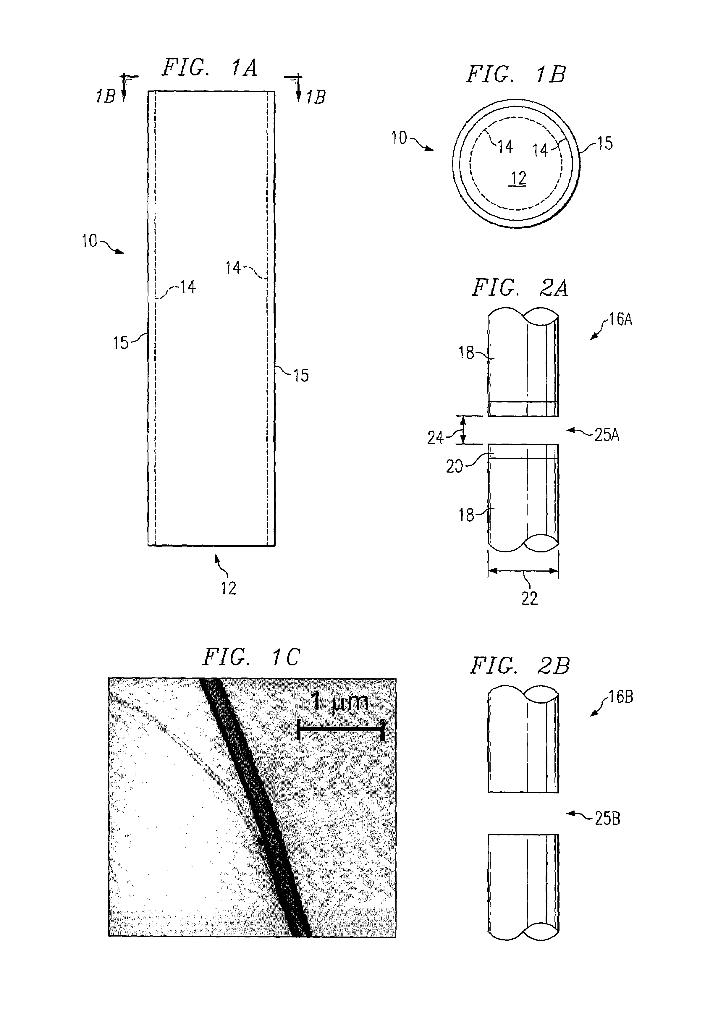
[0027]FIG. 1A is a schematic diagram of a nanotube 10, and FIG. 1B is plan view of nanotube 10 along the lines 1-B of FIG. 1A. As illustrated in FIG. 1A, nanotube 10 is formed with a core section, or pore 12, surrounded by one or more walls 14. In some nanotubes, surrounding the one or more walls 14 is a coating 15. In one embodiment, coating 15 is an amorphous carbon layer; however, if a coating is utilized, any coating that facilitates the manipulation of the nanotube in the subsequent steps as illustrated in FIG. 3, may be used. For example, the coating may improve the visibility of the nanotube under an optical microscope, or improve the mechanical strength of the nanotube so that it will not break easily under mechanical stress that may result from handling or manipulation of the nanotube as illustrated in FIG. 3. The inter...


PUM

PropertyMeasurementUnit
pressureaaaaaaaaaa
sizeaaaaaaaaaa
pore diameteraaaaaaaaaa

Abstract

According to one embodiment an apparatus includes a membrane and at least a portion of a nanotube imbedded within the membrane. The portion of the nanotube imbedded within the membrane provides a conduit through the membrane.

Description

RELATED APPLICATIONS[0001]This application claims the benefit under 35 U.S.C. §119(e) of the filing date of U.S. Provisional Application Ser. No. 60 / 299,399, filed Jun. 18, 2001 entitled Fabrication and Application of Single-Nanopore Membranes.GOVERNMENT RIGHTS[0002]The work described in this patent application was developed under National Science Foundation grants CHE-9796203 and CHE-9818302 and Department of Energy contract No. DE-FG03-01ER15247. The U.S. Government may have certain rights in this patent application.TECHNICAL FIELD OF THE INVENTION[0003]This invention relates in general to nanoparticles, and more particularly to a method and apparatus for nanoparticle transport and detection.BACKGROUND OF THE INVENTION[0004]Transport in nanoporous media differs from ordinary transport in bulk media. Nanoporous material refers generally to material having one or more pores less than one micrometer in size. The differences arise largely because the interactions between the pore surf...

Claims


Application Information

Patent Timeline
Patent Type & Authority Patents(United States)
IPC IPC(8): G01N27/447B01D61/00C12Q1/68F17D1/00G01N27/28
CPCB01D67/0062B01D69/06B01D71/021B01L3/0241B81C1/00087B82Y30/00B01L2300/0896G01N2015/0038B81B2203/0127G01N15/1218B01L2400/0487Y10T137/0318B01D71/0212
Inventor CROOKS, RICHARD M.SUN, LI
Owner TEXAS A&M UNIVERSITY
Why Eureka
Try Eureka