Beam source and beam processing apparatus

a beam processing and beam source technology, applied in the field of beam sources, can solve the problems of difficult to generate uniform beams, inability to process insulated workpieces, and insufficient energy supply to the central area

Inactive Publication Date: 2006-07-18
TOHOKU TECHNO ARCH CO LTD
View PDF14 Cites 14 Cited by
  • Summary
  • Abstract
  • Description
  • Claims
  • Application Information

AI Technical Summary

Benefits of technology

[0019]With the above arrangement, it is possible to uniformly generate various kinds of beams having a large diameter, such as a positive ion beam, a negative ion beam, and a neutral particle beam. In particular, the beam source causes no charge build-up phenomenon and can shield radiation form the plasma. Thus, it is possible to provide a beam source that causes no damage to a workpiece.
[0023]In this case, the beam source may have a container for defining the plasma generating chamber. The container may have a wall which serves as the second electrode. With this arrangement, it is possible to simplify the beam source and reduce the manufacturing cost of the beam source.
[0024]According to a preferred aspect of the present invention, the first electrode serves as a neutralization device for the ions extracted from the plasma. Specifically, the first electrode may comprise an orifice plate having a plurality of orifices for neutralizing the ions extracted from the plasma. With this arrangement, positive ions or negative ions are extracted from the plasma and neutralized into a neutral particle beam. Thus, it is possible to uniformly generate a highly directional neutral particle beam having a large kinetic energy and a large diameter.

Problems solved by technology

When the diameter of a conventional ion beam source is increased so as to generate various kinds of beams including a positive ion beam, a negative ion beam, and a neutral particle beam, the following problems arise.
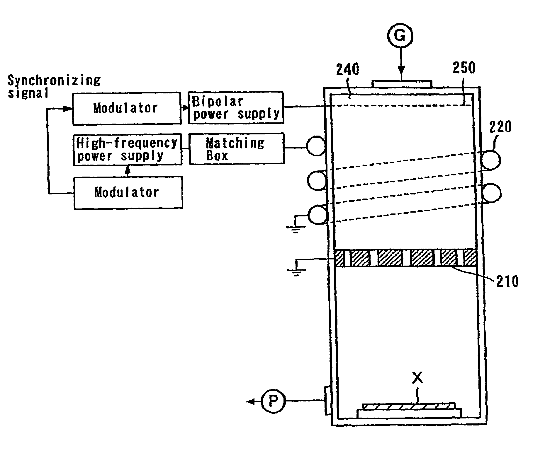
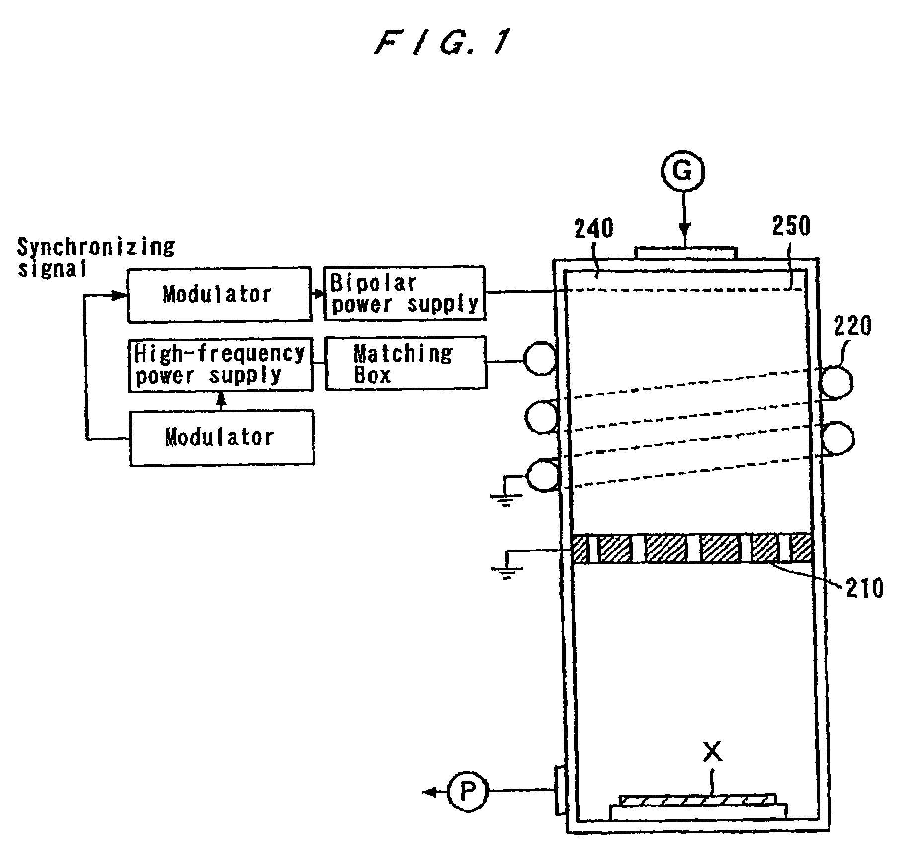
However, when the beam generating chamber 240 is increased in size to generate a beam having a larger diameter, the coil 220 cannot supply sufficient energy to the central area of the beam generating chamber 240.
In such a case, the plasma density becomes non-uniform in the radial direction so as to make it difficult to generate a uniform beam.
In such a beam processing apparatus which applies charged particles to a workpiece, an insulated workpiece cannot be processed because of a charge build-up phenomenon in which electric charges are built up on the workpiece.
Further, since the ion beam emitted from the beam source tends to spread due to the space-charge effect, the workpiece cannot be processed in a fine pattern.
However, since local unbalance of the electric charges still remains on the workpiece, the workpiece cannot be processed in a fine pattern.
In the case where ions are extracted from a plasma source and applied to a workpiece, if a radiation (e.g. an ultraviolet ray) produced by the plasma source is applied to the workpiece, then the radiation adversely affects the workpiece.
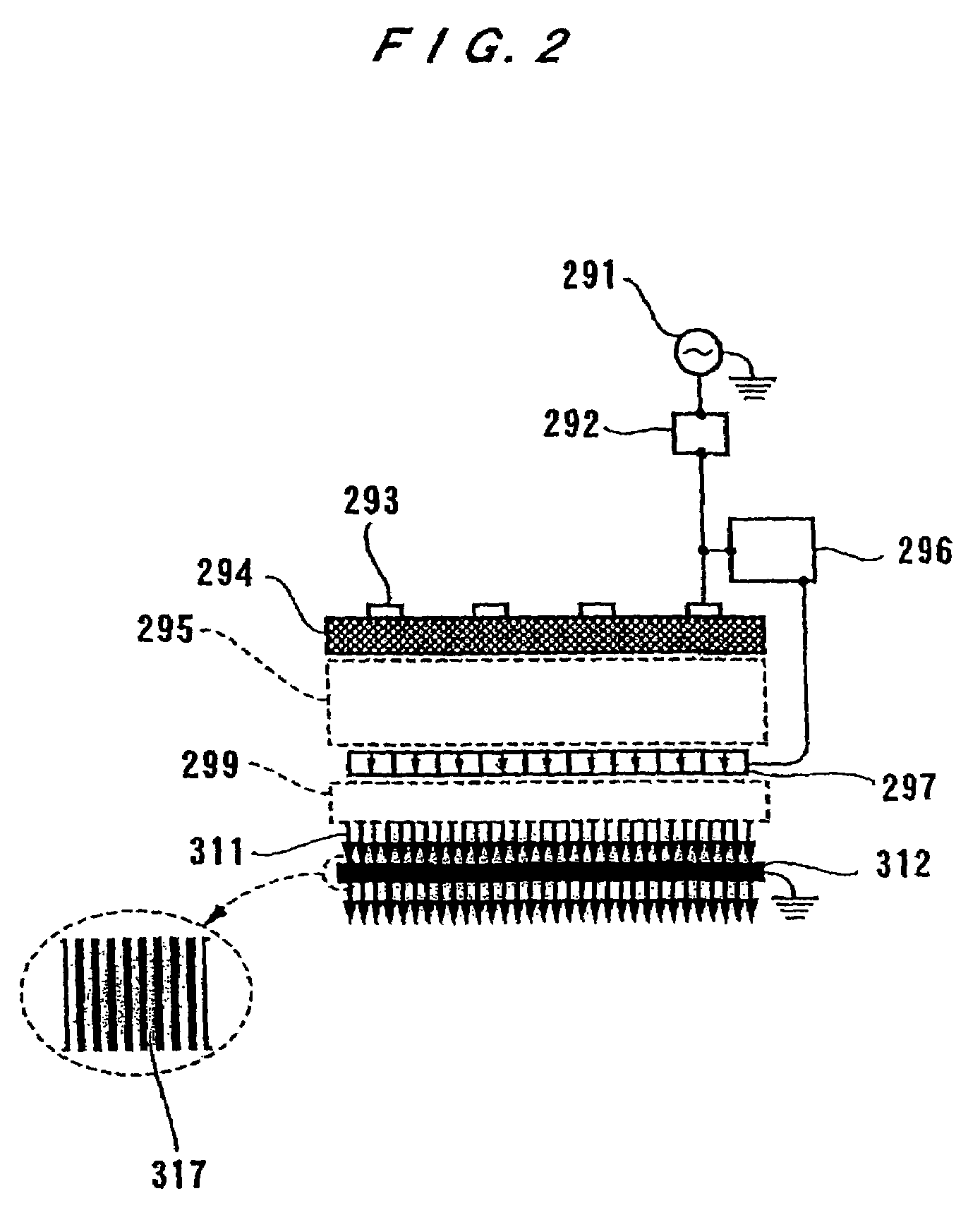
For these purposes, the manufacturing cost rises, and only limited materials can be used for the sub-Debye neutralizer grid 312.
However, because aluminum is likely to deform due to heat, it is an unsuitable material for a beam source having a large diameter of about 10 inches.
Thus, it is difficult to generate a uniform beam having a large diameter with the neutral particle beam generating apparatus as disclosed by U.S. Pat. No. 6,331,701.

Method used


Image

  • Beam source and beam processing apparatus
  • Beam source and beam processing apparatus
  • Beam source and beam processing apparatus

Examples


first embodiment

[0049]FIG. 3A is a schematic view showing a beam source according to the present invention. As shown in FIG. 3A, the beam source has a cylindrical plasma generating chamber 4, a first electrode 1 disposed at a lower end of the plasma generating chamber 4, antennas 2 disposed within the plasma generating chamber 4 for generating plasma in the plasma generating chamber 4, and a second electrode 5 disposed in the plasma generating chamber 4 so as to face the first electrode 1.

[0050]The plasma generating chamber 4 is formed by a container 7 made of quartz glass, ceramics, metal, or the like. Quartz glass emits oxygen when it is exposed to plasma containing fluorocarbon. Accordingly, when the container 7 is made of quartz glass, oxygen is mixed as impurities in a beam so that a beam having desired components cannot be generated. Therefore, when the plasma contains fluorocarbon, the container 7 should be made of a material that emits no oxygen even if it is exposed to fluorocarbon, such a...

second embodiment

[0063]FIG. 4A is a schematic views showing a beam source according to the present invention. As shown in FIG. 4A, the beam source has a plasma generating chamber 14, a first electrode 1 disposed at a lower end of the plasma generating chamber 14, antennas 12 disposed outside of the plasma generating chamber 14 for generating plasma in the plasma generating chamber 14, a second electrode 15 disposed in the plasma generating chamber 14 so as to face the first electrode 1.

[0064]The plasma generating chamber 14 is formed by a container 17 including a cylindrical portion 17a and a truncated conical portion 17b. The container 17 is made of quartz glass, ceramics, metal, or the like. Quartz glass emits oxygen when it is exposed to plasma containing fluorocarbon. Accordingly, when the container 17 is made of quartz glass, oxygen is mixed as impurities in a beam so that a beam having desired components cannot be generated. Therefore, when the plasma contains fluorocarbon, the container 17 sh...

third embodiment

[0076]FIG. 5A is a schematic view showing a beam source according to the present invention. As shown in FIG. 5A, the beam source has a cylindrical plasma generating chamber 4, a first electrode 1 disposed at a lower end of the plasma generating chamber 4, an antenna 22 disposed on an upper surface of the plasma generating chamber 4 for generating plasma in the plasma generating chamber 4, and a second electrode 25 disposed within the plasma generating chamber 4 so as to face the first electrode 1.

[0077]The plasma generating chamber 4 is formed by a container 7 made of quartz glass, ceramics, metal, or the like. Quartz glass emits oxygen when it is exposed to plasma containing fluorocarbon. Accordingly, when the container 7 is made of quartz glass, oxygen is mixed as impurities in a beam so that a beam having desired components cannot be generated. Therefore, when the plasma contains fluorocarbon, the container 7 should be made of a material that emits no oxygen even if it is exposed...


PUM

PropertyMeasurementUnit
diameteraaaaaaaaaa
aspect ratioaaaaaaaaaa

Abstract

A beam source has a plasma generating chamber, an antenna for generating plasma in the plasma generating chamber, a first electrode disposed in the plasma generating chamber, and a second electrode disposed in the plasma generating chamber. Both of the antenna and the second electrode face the first electrode. The beam source also includes a power supply for applying a voltage between the first electrode and the second electrode to extract particles from the plasma generated by the antenna. The beam source applies various kinds of beams having a large diameter, such as a positive ion beam, a negative ion beam, and a neutral particle beam, uniformly to a workpiece.

Description

BACKGROUND OF THE INVENTION[0001]1. Field of the Invention[0002]The present invention relates to a beam source suitable for use in a manufacturing process of semiconductor integrated circuits, information storage media such as hard disks, fine optical elements, micromachines, and the like, and more particularly to a beam source for generating various kinds of highly directional and highly dense beams including a positive ion beam, a negative ion beam, and a neutral particle beam from high-density plasma. The present invention also relates to a beam processing apparatus having such a beam source.[0003]2. Description of the Related Art[0004]In recent years, semiconductor integrated circuits, information storage media such as hard disks, fine optical elements, micromachines, and the like have been processed in highly fine patterns. In fields of processing such workpieces, attention has been attracted to use of a high-density energetic beam which is highly linear, i.e., highly direction...

Claims


Application Information

Patent Timeline
Patent Type & Authority Patents(United States)
IPC IPC(8): H05B31/26C23C16/00H01J27/16H05H1/46H01J37/08H01J37/305H01J37/32H01L21/02H01L21/205H01L21/3065
CPCH01J37/32357H01J37/321
Inventor FUKUDA, AKIRASHIBATA, AKIOHIYAMA, HIROKUNIICHIKI, KATSUNORIYAMAUCHI, KAZUOSAMUKAWA, SEIJI
Owner TOHOKU TECHNO ARCH CO LTD
Why Eureka
Try Eureka