Methods of preparing electrochemical cells

a technology of electrochemical cells and separators, applied in the direction of non-aqueous electrolyte cells, cell components, sustainable manufacturing/processing, etc., can solve the problems of hydroxyl solvents, water and alcohols, typically used with sol gel coatings, coatings,

Inactive Publication Date: 2006-07-25
OPTODOT CORP +1
View PDF30 Cites 98 Cited by
  • Summary
  • Abstract
  • Description
  • Claims
  • Application Information

AI Technical Summary

Problems solved by technology

Cracking of the coated separator layer may lead to short circuiting of the cell.
Also, when a separator layer is coated directly onto an anode comprising a reactive material, such as lithium metal, the composition of the applied separator coating must be unreactive to the anode.
Thus, the hydroxylic solvents, such as water and alcohols, typically used with sol gel coatings, such as coatings of a pseudo-boehmite sol to form a microporous separator layer, are too reactive for direct application onto a lithium metal anode.

Method used


Image

  • Methods of preparing electrochemical cells
  • Methods of preparing electrochemical cells
  • Methods of preparing electrochemical cells

Examples


example 1

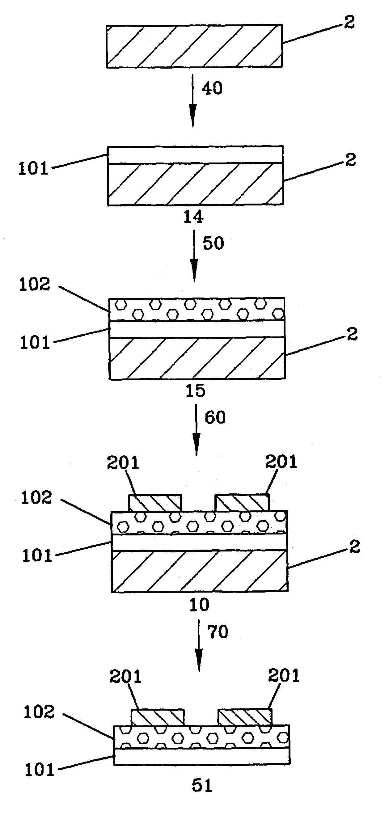
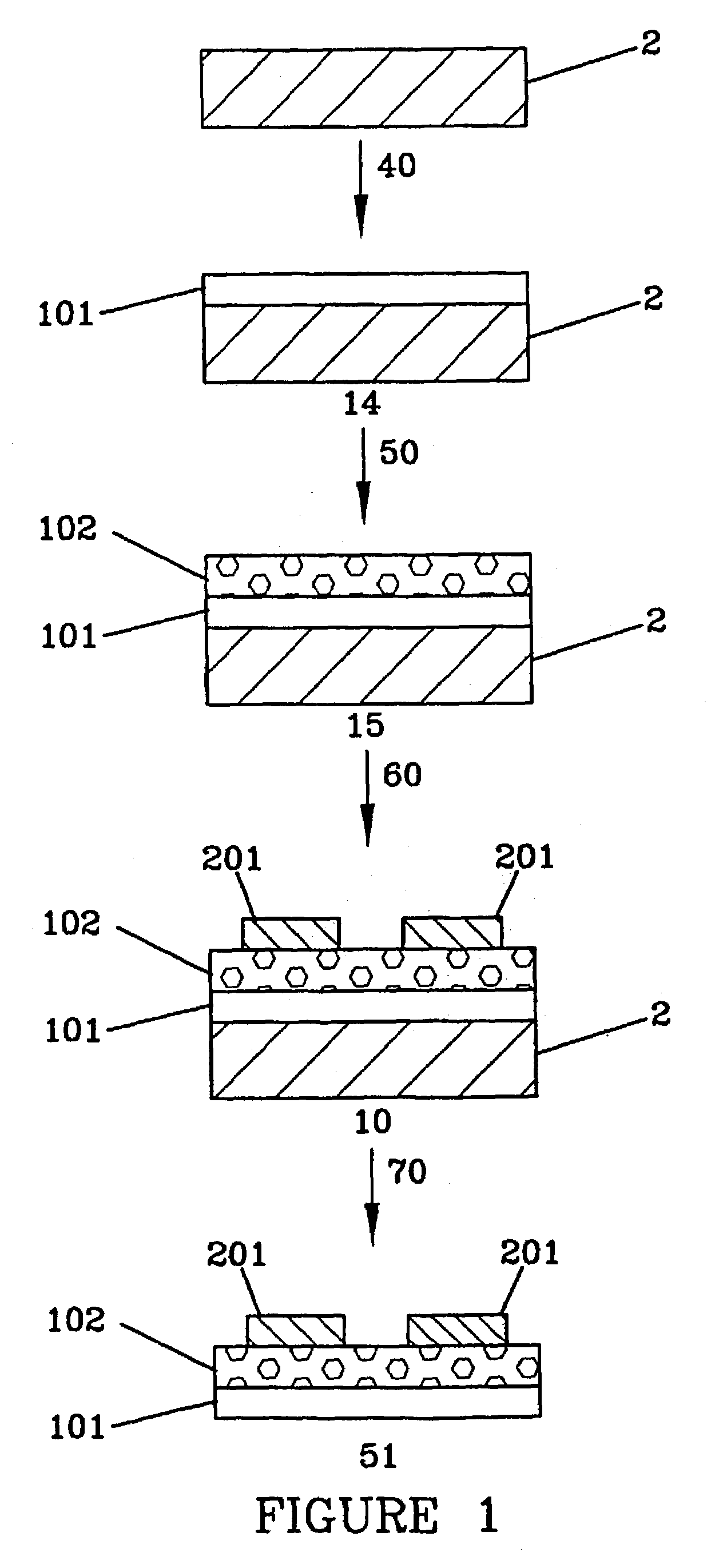
[0199]A coating mixture for a first step of making a protective coating layer was prepared by adding 17.5 g of a 4% by weight solution of polyvinyl alcohol (AIRVOL 125, a trademark for polyvinyl alcohol polymers available from Air Products, Inc., Allentown, Pa.) in water to 10.0 g of a 7.0% by weight solids solution of boehmite sol in water (CATALOID AS-3, a trademark for aluminum boehmite sols available from Catalysts & Chemicals Ind. Co., Ltd., Tokyo, Japan) and stirring to mix the materials. 0.10 g of ZONYL FSO-100, a trademark for non-ionic fluorochemical compounds available from E.I. duPont de Nemours, Wilmington, Del., was added with stirring to make the sol gel coating mixture. Using a gap coating with a slot opening of a set thickness to doctor the coating, the sol gel coating mixture was applied to the non-treated surface of 23 micron thick MELINEX 6328, a trademark for polyethylene terephthalate (PET) films available from DuPont Teijin Films, Wilmington, Del. After air dry...

example 2

[0205]A free-standing cathode / separator assembly was prepared as described in Example 1, except that a 5% solution of styrene-4-sulfonic acid sodium salt (available from Aldrich Chemical Company, Milwaukee, Wis.) was substituted for the multifunctional monomer coating mixture with the latent lithium ion catalyst. This free-standing cathode / separator assembly of Example 2 gave similar results when fabricated into rechargeable electrochemical cells as those found with the cathode / separator assembly of Example 1.

example 3

[0206]A free-standing cathode / separator assembly was prepared as described in Example 1, except that a 7.0% by weight solids solution of ammonium zirconyl carbonate prepared by adding water to BACOTE 20, a trademark for zirconium compounds available from Magnesium Eleckton, Flemington, N.J., was substituted for the CATALOID AS-3 in both the first step of making the protective coating layer and in the step of making the microporous xerogel separator layer. The ammonium zirconyl carbonate is a precursor to zirconium oxide sols and, upon coating and drying, provides a zirconium oxide xerogel layer. This free-standing cathode / separator assembly of Example 3 showed more than twice the mechancial strength and flexibility without cracking as found with the free-standing cathode / separator assembly of Example 1. The free-standing cathode / separator assembly of Example 3 gave similar results when fabricated into rechargeable electrochemical cells as those found with the cathode / separator assem...


PUM

PropertyMeasurementUnit
thicknessesaaaaaaaaaa
thicknessaaaaaaaaaa
thicknessaaaaaaaaaa

Abstract

Methods of preparing a cathode / separator assembly for use in electrochemical cells in which a protective coating layer is coated on a temporary carrier substrate, a microporous separator layer is then coated on the protective coating layer, and a cathode is then coated or laminated on the separator layer, prior to removing the temporary carrier substrate from the protective coating layer. Also, methods of preparing electrochemical cells utilizing cathode / separator assemblies prepared by such methods, and cathode / separator assemblies and electrochemical cells prepared by such methods.

Description

CROSS-REFERENCE TO RELATED APPLICATIONS[0001]This application is the U.S. National Phase of International Application PCT / US00 / 32233, filed on 21 Nov. 2000, which claims priority to U.S. Provisional Application Nos. 60 / 167,150 and 60 / 167,149, both of which were filed 23 Nov. 1999.TECHNICAL FIELD[0002]The present invention relates generally to the fields of electrochemical cells and of separators for use in electrochemical cells. More particularly, this invention pertains to methods of preparing electrochemical cells and subassemblies of electrochemical cells comprising steps in which a microporous separator layer is coated on a temporary carrier substrate and a cathode active layer or an anode active layer is then coated overlying the separator layer, prior to removing the temporary carrier substrate from the separator layer. Alternatively, instead of coating, the cathode or the anode may be laminated to the surface of the microporous separator layer. One or more protective coating ...

Claims


Application Information

Patent Timeline
Patent Type & Authority Patents(United States)
IPC IPC(8): H01M6/00H01M4/13H01M4/139H01M4/58H01M6/10H01M6/16H01M10/052H01M10/058H01M10/36H01M50/403H01M50/414H01M50/437H01M50/449
CPCH01M2/1686H01M4/13H01M4/5815H01M10/052H01M10/058H01M2/1653H01M2/145H01M4/136H01M4/137H01M4/602H01M2/1673H01M2/1646Y10T29/49115H01M6/10H01M6/16Y02E60/122H01M10/0587Y02E60/10H01M50/403H01M50/46H01M50/449Y02P70/50H01M50/437H01M50/414
Inventor CARLSON, STEVEN A.
Owner OPTODOT CORP
Why Eureka
Try Eureka