Electroconductive contact unit

a contact unit and electroconductor technology, applied in the direction of coupling device connection, superimposed coating process, instruments, etc., can solve the problems of increasing the running cost, affecting the service life of the contact unit, so as to prevent peeling, improve service life, and high electroconductivity

Inactive Publication Date: 2006-07-25
NHK SPRING CO LTD
View PDF19 Cites 6 Cited by
  • Summary
  • Abstract
  • Description
  • Claims
  • Application Information

AI Technical Summary

Benefits of technology

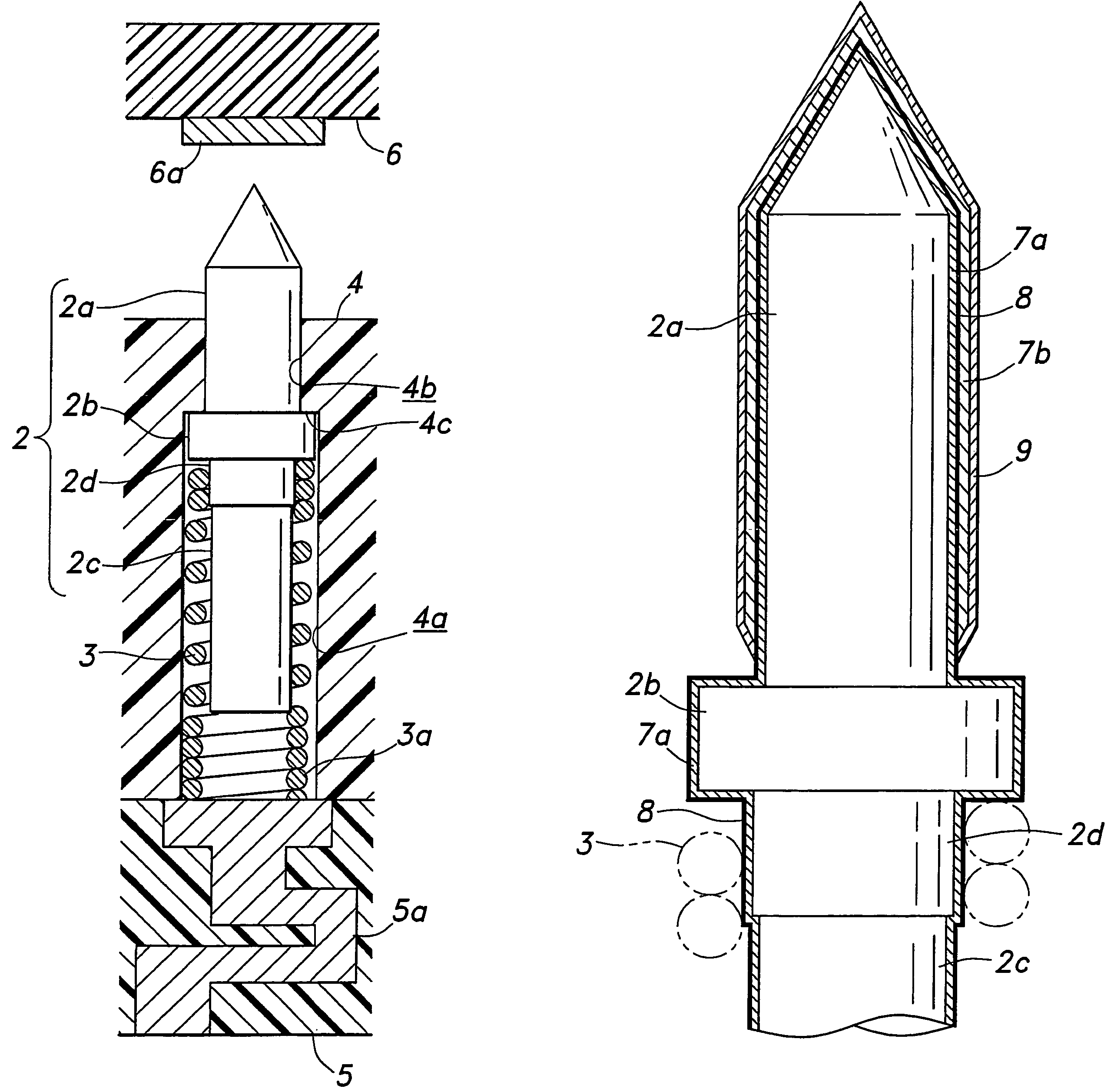
[0012]If the gold plating is formed over the entire surface of the needle member, and the iridium, titanium nitride, rhodium, hafnium nitride or alloy of any one of them with gold or platinum is provided via an under layer for preventing peeling, the gold plating that is provided over the entire surface of the needle member ensures a high electroconductivity for the needle member as whole, and the under layer ensures a strong attachment of the material such as iridium to the needle member. Also, the gold plated layer under the material such as iridium conducts electricity, and provides an even more fa

Problems solved by technology

When the object to be tested consists of a component made of a hard material such as those mentioned earlier, and the contact probe uses needle members made of conventional SK material (carbon tool steel), repeated use of the needle members will result in th

Method used


Image

  • Electroconductive contact unit
  • Electroconductive contact unit
  • Electroconductive contact unit

Examples


Embodiment Construction

[0022]Preferred embodiments of the present invention are described in the following with reference to the appended drawings.

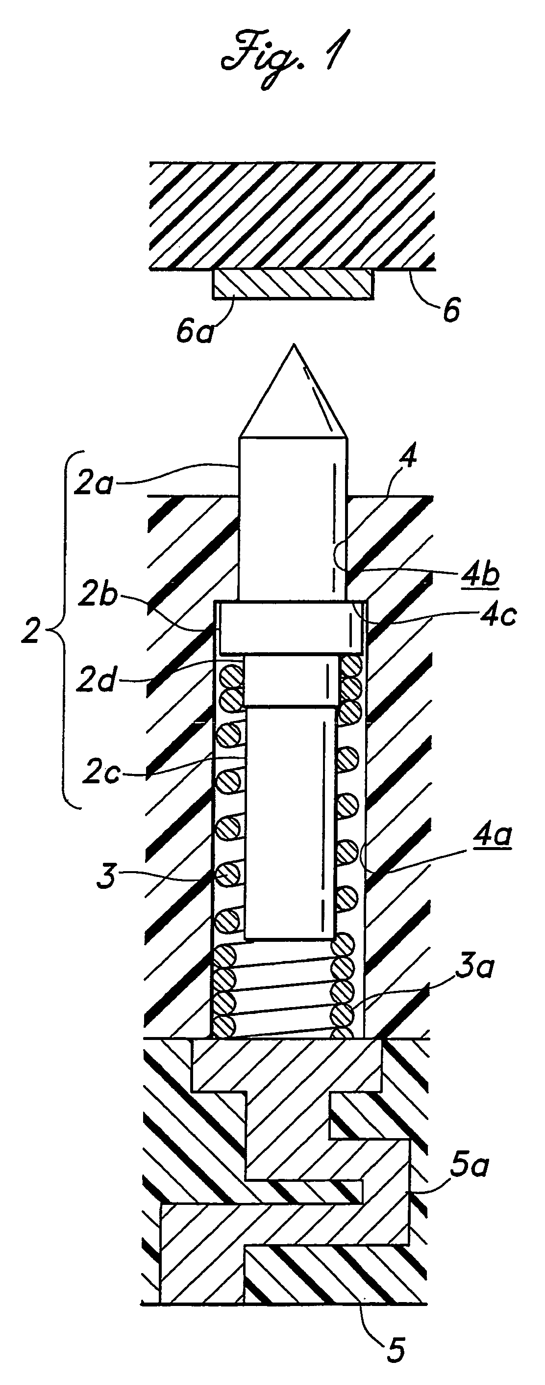
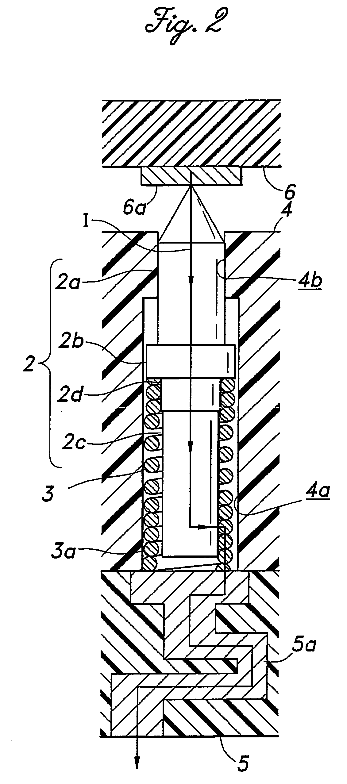
[0023]FIG. 1 is a vertical sectional view showing an electroconductive contact unit 1 for use in a contact probe embodying the present invention. This electroconductive contact unit 1 may be used by itself, but is particularly suitable for use in a holder (probe head) of a multipoint contact probe as one of a large number of similar electroconductive contact units that are arranged one next to another, for instance for a wafer level test. In such a contact probe, the holder is integrally attached to a board mounted on a testing machine via a relay circuit board. The drawing is for illustration purpose only, and the actual aspect ratio may differ from that of the illustrated example.

[0024]The electroconductive contact unit 1 comprises an electroconductive needle member 2, a compression coil spring 3 and a holder 4 made of electrically insulating material and def...


PUM

PropertyMeasurementUnit
Electrical resistanceaaaaaaaaaa
Electrical conductoraaaaaaaaaa

Abstract

In the electroconductive contact unit of the present invention, a gold plated layer 8 is formed over the surface of an electroconductive needle member 2 via a Ni under layer 7a, and a layer of iridium (titanium nitride, rhodium or hafnium nitride) is formed on the gold plated layer 8 of the needle portion 2a by sputtering, via an Ni under layer 7b. Thereby, the tip portion is provided with an improved resistance to oxidization and wear without using any special material for the needle member, and the durability of the needle member is improved so that the running cost can be minimized.

Description

CROSS-REFERENCE TO RELATED APPLICATIONS[0001]This application is a National Phase Application of PCT International Application No. PCT / JP02 / 06647, International Filing Date Jul. 1, 2002, claiming priority of Japanese Patent Application JP 2001-210262, filed 02 Jul. 2001.TECHNICAL FIELD[0002]The present invention relates to an electroconductive contact unit for exchanging signals with printed circuit boards, electronic devices or the likes.BACKGROUND OF THE INVENTION[0003]A conventional electroconductive contact unit for use in contact probes for electrically testing conductor patterns of printed circuit boards and electronic devices typically comprises an electroconductive needle member and a tubular holder that receives the needle member in an axially moveable manner, and the needle member is resiliently urged by a coil spring in the direction to project the tip of the needle member from the front end of the holder so that the tip of the needle member may be resiliently brought int...

Claims


Application Information

Patent Timeline
IPC IPC(8): G01R31/02G01R31/00C23C28/00C23C28/02G01R1/067G01R3/00H01R13/03H01R13/24
CPCC23C28/023G01R1/06722H01R13/03H01R13/2421G01R1/06738H01R2201/20G01R3/00G01R1/06761H01R13/15
Inventor KAZAMA, TOSHIO
Owner NHK SPRING CO LTD
Why Eureka
Try Eureka