Liquid crystal display device with alignment layer including a diamine component and treated by UV irradiation

Inactive Publication Date: 2006-07-25
SHARP KK
View PDF10 Cites 16 Cited by
  • Summary
  • Abstract
  • Description
  • Claims
  • Application Information

AI Technical Summary

Benefits of technology

[0028]In this construction, the bank structures prevent the disturbance of alignment of a liquid crystal

Problems solved by technology

When the alignment layer is rubbed with the fiber material, however, the fiber material scatters, and the liquid crystal panel may be contaminated.
In this case, a transverse electric field acts between the pixel electrode and the bus line, and a problem develops that this electric field disturbs the alignment of the liquid crystal at the boundary portion between the pixel electrode and the bus line.
In consequence, stable alignment cannot be achieved and excellent display cannot be provided as domains

Method used


Image

  • Liquid crystal display device with alignment layer including a diamine component and treated by UV irradiation
  • Liquid crystal display device with alignment layer including a diamine component and treated by UV irradiation
  • Liquid crystal display device with alignment layer including a diamine component and treated by UV irradiation

Examples


Example

EXAMPLE 1

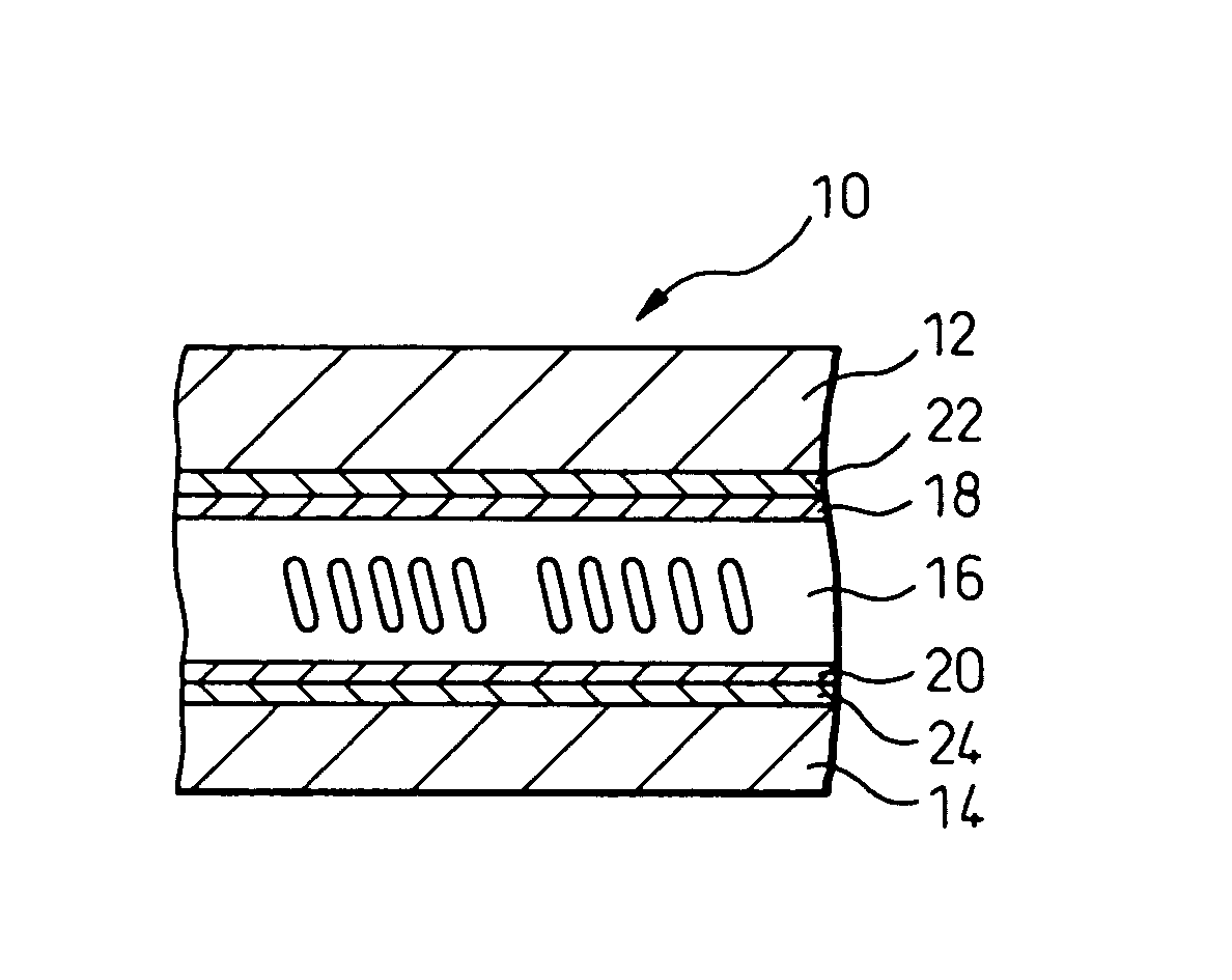
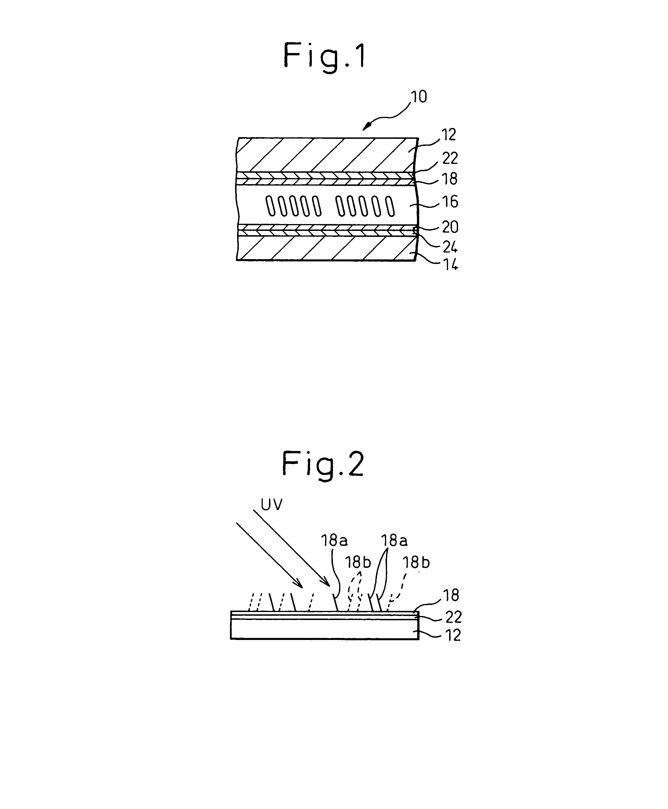
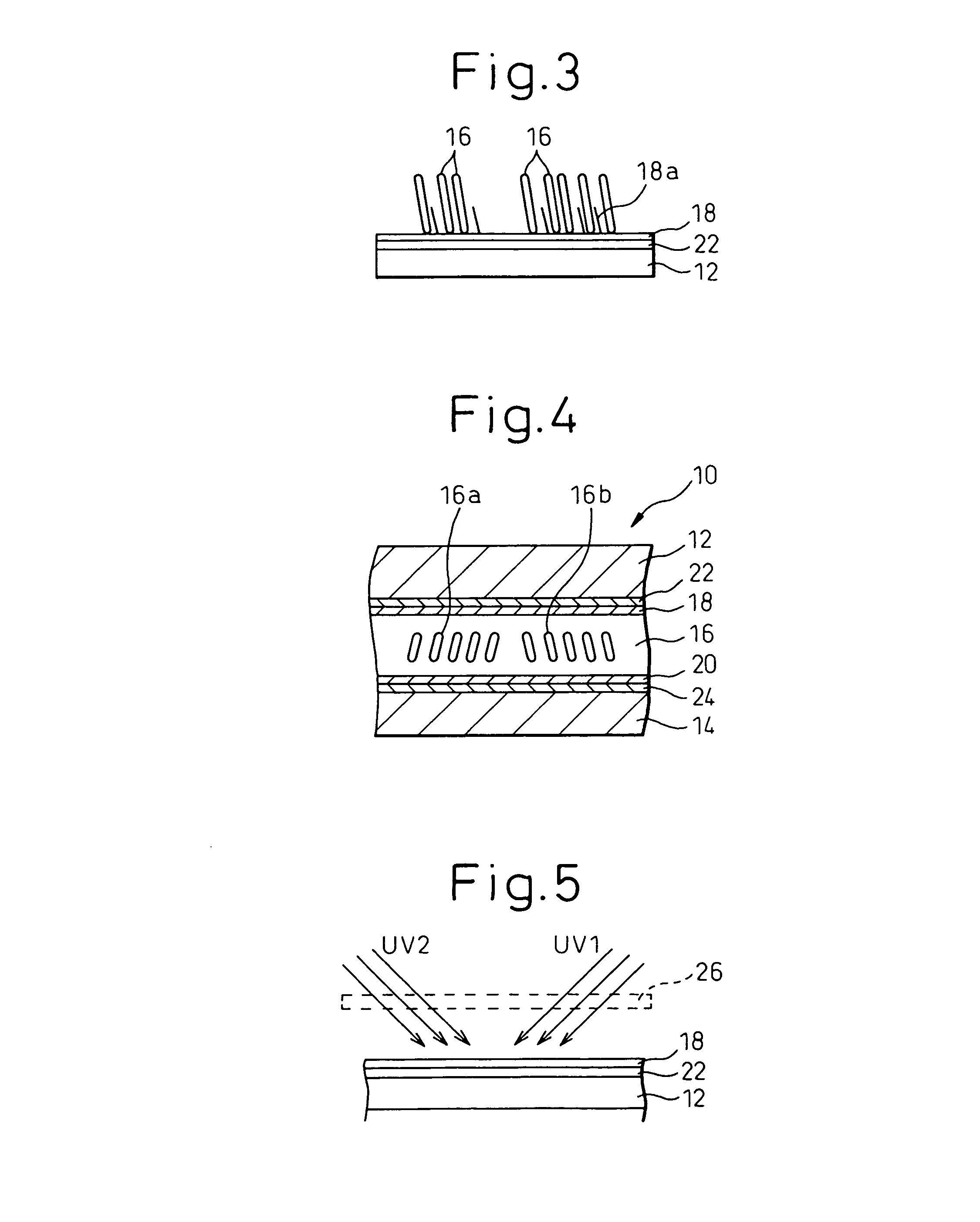
[0079]Alignment layers 18 and 20 are prepared from a mixture of polyamic acid A and polyimide H (having a 90% content of diamine component contributing to vertical alignment). The mixing ratio is polyamic acid A:polyimide H=49:1. The alignment layer material containing this mixture is applied by using a spinner and is baked to form the alignment layers 18 and 20 on the substrates 12 and 14. Ultraviolet light is irradiated onto the alignment layers 18 and 20 in the oblique direction. Incidentally, several samples are prepared by changing the irradiation quantity of the ultraviolet light. A thermosetting sealant is applied to one of the substrates and spacers of 4 μm are scattered on the other substrate, and both substrates are then joined. After vacuum packing, thermosetting is conducted to form an empty cell. A liquid crystal having negative dielectric anisotropy is charged into this empty cell in vacuum environment to form a liquid crystal display panel. A pretilt angle of...

Example

EXAMPLE 2

[0080]The alignment layers 18 an 20 are prepared from a mixture of polyamic acid B having a surface energy change shown in FIG. 8 and polyimide G (having a 60% content of a diamine component contributing to vertical alignment). The mixing ratio is polyamic acid B:polyimide G=4:1. An alignment layer material containing this mixture is used to produce a liquid crystal display panel in the same way as in Example 1. A pretilt angle of the liquid crystal panel thus produced is measured. As represented by curve GB in FIG. 7, the pretilt angle attains minimum at an irradiation quantity 3J of the ultraviolet light, and the change of the pretilt angle is considerably small before and after this minimum value. In this way, a stable pretilt angle can be obtained. Surface energy hardly changes, either, as shown in FIG. 8.

Example

EXAMPLE 3

[0081]Alignment layers 18 and 20 are prepared from a mixture of polyamic acid C having a surface energy change shown in FIG. 9 and polyimide F (having a 50% content of a diamine component contributing to vertical alignment). The mixing ratio is polyamic acid C:polyimide F=3:1. An alignment layer material containing this mixture is used to produce a liquid crystal display panel in the same way as in Example 1. A pretilt angle of the liquid crystal panel thus produced is measured. As represented by curve FC in FIG. 7, the pretilt angle attains about 88° at an irradiation quantity of 2J to 3J of the ultraviolet light, and the change of the pretilt angle hardly exists. In this way, a stable pretilt angle can be obtained. As shown in FIG. 8, the change of the voltage relative retention is small, and an excellent voltage relative retention can be acquired.

COMPARATIVE EXAMPLE

[0082]Alignment layers 18 and 20 are prepared from a mixture of polyamic acid A and polyimide D (having a 2...


PUM

PropertyMeasurementUnit
Fractionaaaaaaaaaa
Lengthaaaaaaaaaa
Lengthaaaaaaaaaa

Abstract

A liquid crystal display device includes a pair of substrates, a liquid crystal between substrates and alignment layers disposed on the inner surface sides of the substrates. The alignment layer is made from a material including polyamic acid containing a diamine component and polyimide containing a diamine component different from the diamine component of the polyamic acid. The alignment layer is subjected to alignment treatment by irradiation of light. UV light can be irradiated in the oblique direction onto the alignment layer through a mask having openings. A reflecting plate can be arranged between a UV light source and the mask. Also, bank structures having a thickness from 0.1 to 0.15 μm can be provided on the alignment layer of the TFT substrate.

Description

BACKGROUND OF THE INVENTION[0001]1. Field of the Invention[0002]The present invention relates to a liquid display device in which light is irradiated onto an alignment layer or bank structures are provided, for controlling the alignment of the liquid crystal. The present invention also relates to an exposure apparatus of an alignment layer of a liquid crystal display device and a treatment method of an alignment layer.[0003]2. Description of the Related Art[0004]A liquid crystal display device includes a liquid crystal that is sandwiched between a pair of substrates, and an electrode for applying an electric field to the liquid crystal and an alignment layer for controlling the alignment of the liquid crystal are arranged on the inner surface side of each substrate. The alignment layer is treated for realizing the alignment of the liquid crystal molecules in a predetermined direction. Typically, the alignment layer is rubbed by a fiber material such as rayon, and the liquid crystal ...

Claims


Application Information

Patent Timeline
IPC IPC(8): G02F1/141G02F1/1337
CPCG02F1/1303G02F1/133723G02F1/133788G03F7/22Y10T428/1018Y10T428/1023G02F2201/086C09K2323/025C09K2323/027
Inventor CHIDA, HIDEOYOSHIDA, HIDEFUMITASAKA, YASUTOSHI
Owner SHARP KK
Why Eureka
Try Eureka