Method and system for correcting sensor offsets

Active Publication Date: 2006-08-01
FORD GLOBAL TECH LLC
View PDF236 Cites 31 Cited by
  • Summary
  • Abstract
  • Description
  • Claims
  • Application Information

AI Technical Summary

Benefits of technology

[0010]One advantage of the invention is that readings from vehicle dynamic sensors are more accurate.
[0011]Other objects and features of the present invention will b

Problems solved by technology

During various different phases of vehicle operation, the aforementioned sensors t

Method used


Image

  • Method and system for correcting sensor offsets
  • Method and system for correcting sensor offsets
  • Method and system for correcting sensor offsets

Examples


Embodiment Construction

[0015]In the following figures the same reference numerals are used to identify the same components.

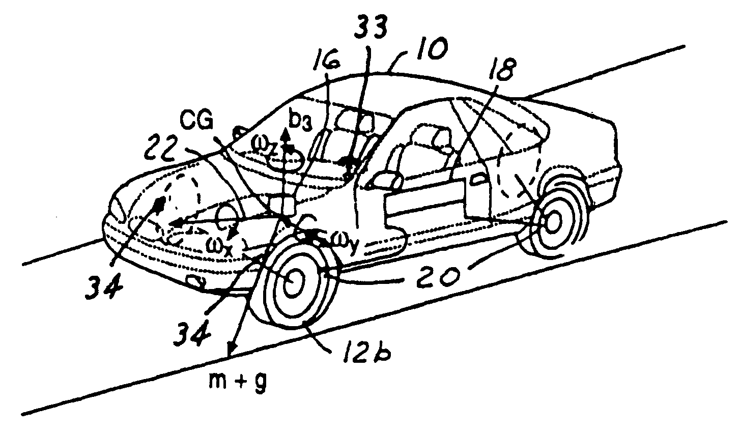
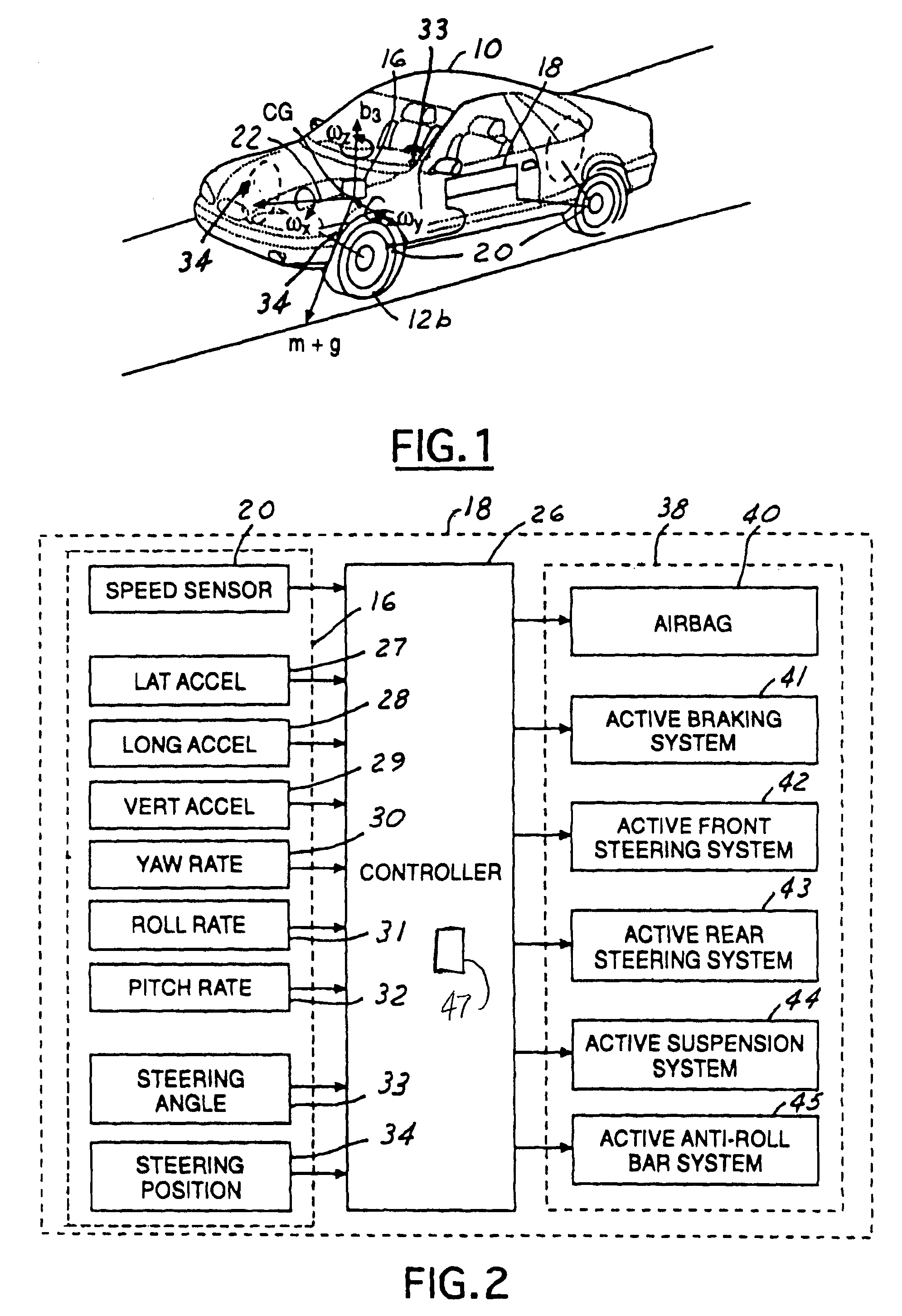
[0016]Referring to FIGS. 1 and 2, a control system 18 for an automotive vehicle 19 having a sensing system 16 (sensor cluster) and a controller 26, is illustrated. Various forces and moments are acting thereon during a rollover condition.

[0017]The vehicle control system 18 includes the sensor system 16. The sensing system 16 may use a six control sensor set including three axial accelerometers including a lateral accelerometer 27 (generating a lateral acceleration signal), a longitudinal accelerometer 28 (generating a longitudinal acceleration signal), and a vertical accelerometer 29 (generating a vertical acceleration signal) and three axial rotation rate detectors including a yaw rate sensor 30 (generating a yaw rate signal), a roll rate sensor 31 (generating a roll rate signal), and a pitch rate sensor 32 (generating a pitch signal). Of course, those skilled in the art will recogni...


PUM


Abstract

A control system (18) for an automotive vehicle (19) having a vehicle body includes a cluster (16) of vehicle dynamic sensors (27, 28, 30, 31), the output signals from the sensors (Yaw Rate Sensor, Roll Rate Sensor, Longitudinal Acceleration Sensor, Lateral Acceleration Sensor) are corrected for errors by removing the zero output DC bias. Such bias constitutes an error that may occur as a result of temperature changes, manufacturing defects, or other factors. The system (18) also compensates for the drift in the sensor output signals that occur during vehicle operation.

Description

RELATED APPLICATIONS[0001]The present invention claims priority to provisional application No. 60 / 401,417 filed on Aug. 5, 2002.TECHNICAL FIELD[0002]The present invention relates generally to a dynamic behavior control apparatus for an automotive vehicle, and more specifically, to a method and apparatus for correcting offsets in vehicle dynamic sensors.BACKGROUND[0003]Dynamic control systems for automotive vehicles have recently begun to be offered on various products. Typical dynamic control systems include sensors corresponding to various vehicle dynamics. Examples thereof include: a yaw rate sensor, a roll rate sensor, a longitudinal acceleration sensor, and a lateral acceleration sensor. Typical dynamic control systems also include a controller that receives the sensor signals and controls various safety and stability systems in response thereto.[0004]During various different phases of vehicle operation, the aforementioned sensors tend to generate errors that may result in false...

Claims


Application Information

Patent Timeline
IPC IPC(8): G06F7/00B60G17/017B60G17/0185B60G17/0195B60T8/172B60T8/88G01C21/10G01C25/00
CPCB60G17/0185G01C25/00B60T8/172B60T8/885G01C21/10B60G17/0195B60G2400/0521B60G2400/0532B60G2400/0533B60G2400/102B60G2400/104B60G2400/106B60G2400/204B60G2400/41B60G2600/082B60G2800/012B60G2800/702B60G2800/91B60G2800/9122B60G2800/92B60G2800/96B60G2800/962B60T2250/06
Inventor SAMUEL, STEPHEN VARGHESEBROWN, TODD ALLEN
Owner FORD GLOBAL TECH LLC
Why Eureka
Try Eureka