

Pulse signal circuit, parallel processing circuit, pattern recognition system, and image input system
a signal circuit and parallel processing technology, applied in the field of pulse signal circuits, parallel processing circuits, pattern recognition systems, image input systems, can solve the problems of reducing the size of the wiring portion related to inter-neuron connections, and the difficulty of applying the layout of respective components to a general pattern recognition
- Summary
- Abstract
- Description
- Claims
- Application Information
AI Technical Summary
Benefits of technology
Problems solved by technology
Method used
Image

Examples
first embodiment
[0037]One preferred embodiment of the present invention will hereinafter be described in detail with reference to the accompanying drawings.
Outline of Whole Architecture
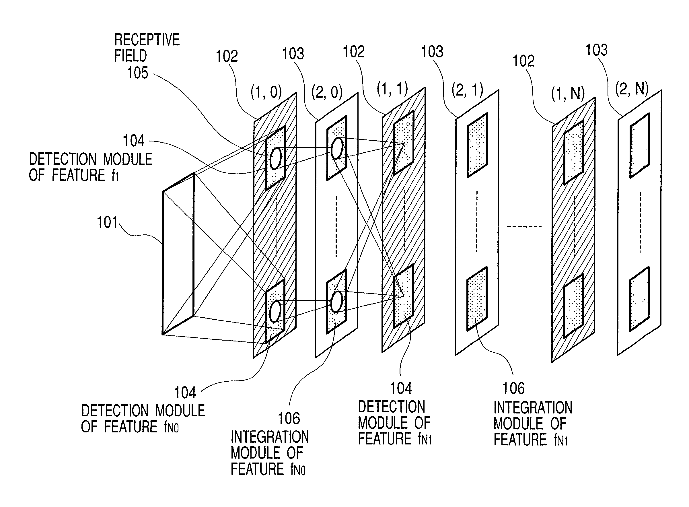
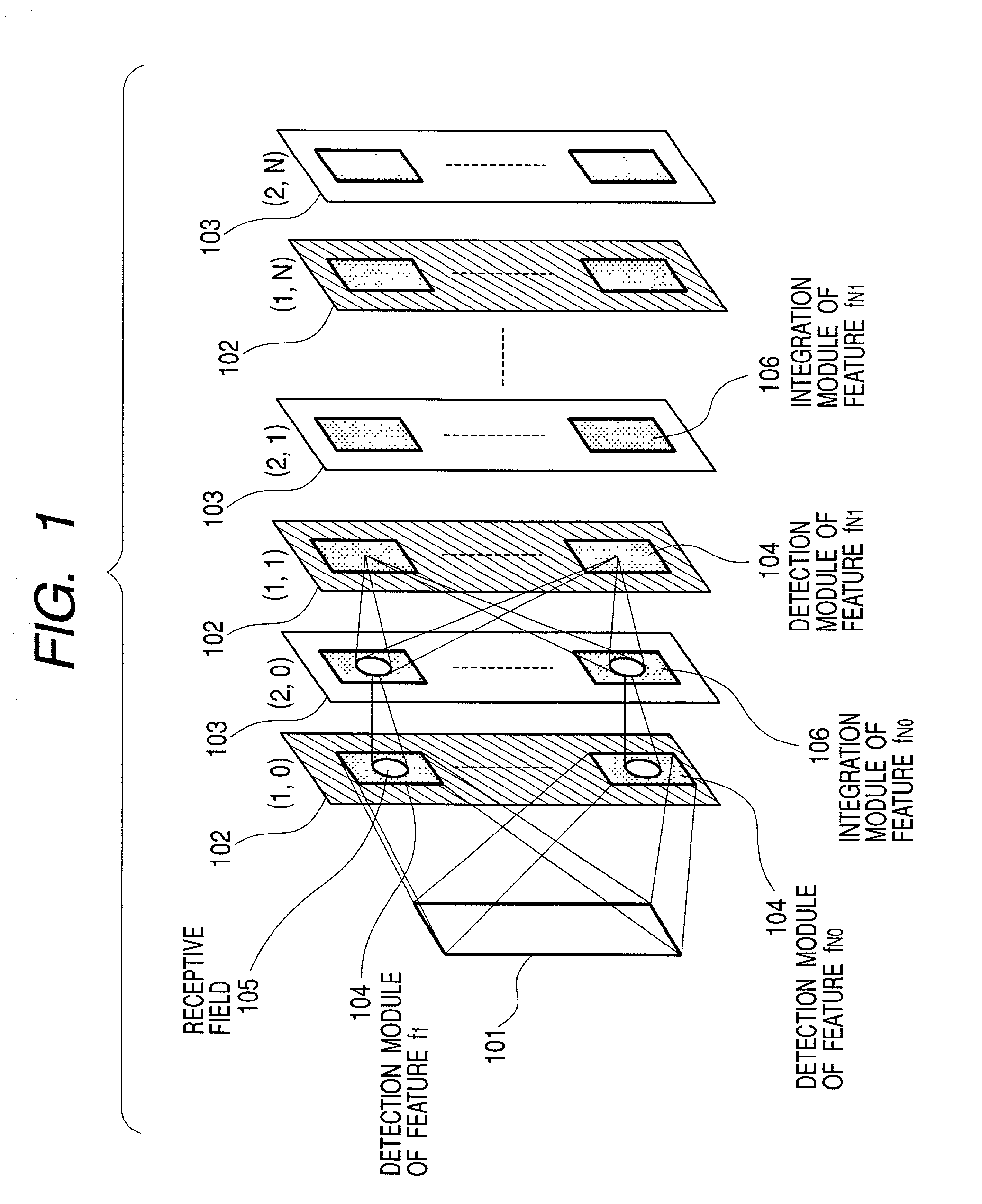
[0038]FIG. 1 is a diagram showing a whole architecture of a network for a pattern detection / recognition system in the first embodiment. This pattern detection / recognition system mainly deals with information related to a recognition (detection) of an object or a geometrical feature.
[0039]FIG. 1 illustrates a so-called convolutional network architecture (LeCun, Y. and Bengio, Y., 1995, “Convolutional Networks for Images Speed, and Time Series” in Handbook of Brain Theory and Neural Networks (M. Arbib, Ed.), MIT Press, pp. 255–258). A different point from the prior arts is, however, that inter-layer connections within the same route can take a form of local interconnections (which will hereinafter be described). A final output is defined as a result of the recognition, i.e., a category of the object recognized.
[0040]A ...
second embodiment
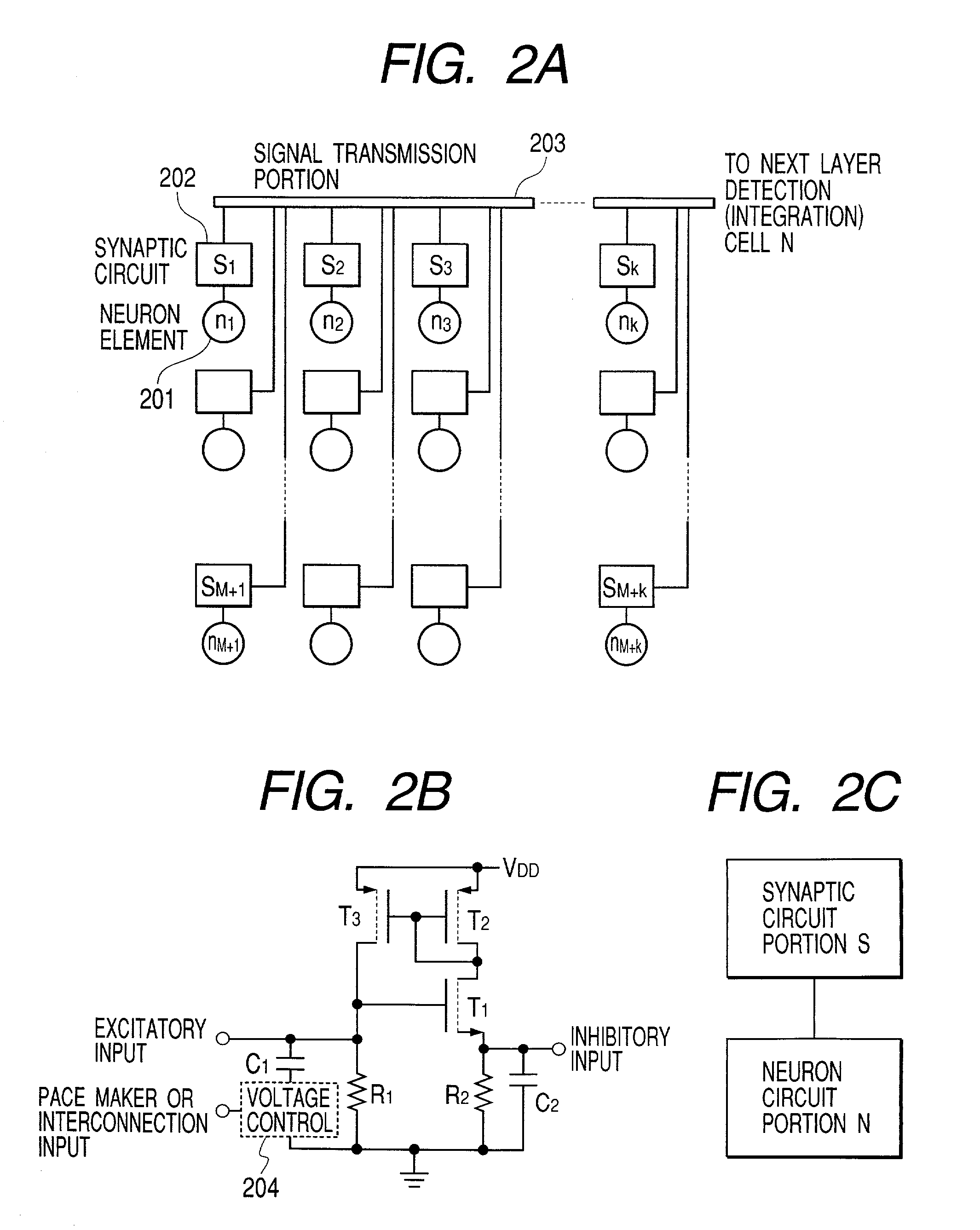
[0139]According to a second embodiment, as shown in FIG. 11B, a branch circuit for outputting in branch the outputs from the synaptic circuits is set as a characteristic component by use of a local timing generation element (or pacemaker neuron) PN as shown in FIG. 11B. The branch circuit has a demultiplexer-wise function as will be exemplified in an embodiment that follow. The branch circuit outputs the output from each of the synaptic circuits to each of the different feature detection layer neurons in accordance with the timing signal transmitted from the local timing generation element. This scheme enables farther wires from the synaptic circuits to be more simplified than in the architecture in the embodiment 1.
[0140]For instance, supposing that the timing generation element generates a low-frequency pulse signal having a smaller pulse width than a period of the pulse train, the branch circuit is structured to output, to the feature integration layer neuron intrinsic to the tim...
third embodiment
[0141]A third embodiment involves the use of a circuit, as a synaptic circuit, incorporating a demultiplexer function together that sets variable a modulation amount at the delay element of the synaptic circuit, controls the modulation (delay) amount of the pulse signal on the basis of the timing signal from the local timing element and branches by switching the output pulses. With this architecture adopted, by contrast with the architecture in the embodiment discussed above in which the synaptic circuit giving the different delay amount is formed independently as the circuit that is at least physically different, even such a synaptic circuit is shared in a time-sharing manner, thereby scheming to further downsize the circuit scale. Note that the process of the neuron receiving the signal having undergone the modulation in the synaptic circuit is the same as in the embodiment 1.
[0142]As shown in FIG. 12, a synaptic circuit S as a simplified version of the circuit architecture in FIG...
PUM
 Abstract
Description
Claims
Application Information