Device having a flow channel containing a layer of wicking material

a technology of flow channel and wicking material, which is applied in the direction of sedimentation separation, enzymology, biomass after-treatment, etc., can solve the problems of slow uptake of viscous fluid, e.g., whole blood, and time-consuming steps of applying a layer of mesh,

Active Publication Date: 2006-08-08
ABBOTT DIABETES CARE INC
View PDF12 Cites 165 Cited by
  • Summary
  • Abstract
  • Description
  • Claims
  • Application Information

AI Technical Summary

Benefits of technology

[0023]In a preferred embodiment, the flow channel is closed at the distal end and has no openings in the sidewalls. In this embodiment, the sensor can be vented through the cover layer by at least one, and preferably a plurality of, openings formed therein. The use of a plurality of openings in the cover layer eliminates the problem that results from the use of a single opening that is improperly positioned with respect to the flow channel, with the result that the opening does not connect the flow channel with the external environment. If two or more openings are employed, and if these openings are separated from one another, there is a higher probability that at least one of the openings will serve to vent air from the flow channel. The openings are preferably placed sufficiently close to each other so that no matter how the cover layer is placed over the flow channel, at least one opening, and preferably more than one opening, is positioned over the flow channel to allow venting. At the same time, the openings are preferably separated by sufficient distance so that the mechanical strength of the cover layer is not diminished.

Problems solved by technology

When the dimensions of the channel are so small as to reduce the volume of fluid that can be transported in a given period of time, the rapid uptake of viscous fluids, e.g., whole blood, becomes a problem.
Applying a layer of mesh is a time-consuming step, and a sensor employing a layer of mesh may require a larger sample than does a sensor not employing a layer of mesh, primarily because a flow channel having greater dimensions may be required to insert a layer of mesh.
In additional, the layer of mesh blocks a portion of the sample from reaching the electrodes, thereby resulting in a lower than desired signal.
The devices in the art described above either require large volumes of sample on account of the construction of the reaction site in mesh-containing sensors or lack adequate uptake of sample on account of extremely small dimensions in a sensor utilizing flow in a capillary channel.

Method used


Image

  • Device having a flow channel containing a layer of wicking material
  • Device having a flow channel containing a layer of wicking material
  • Device having a flow channel containing a layer of wicking material

Examples


example 1

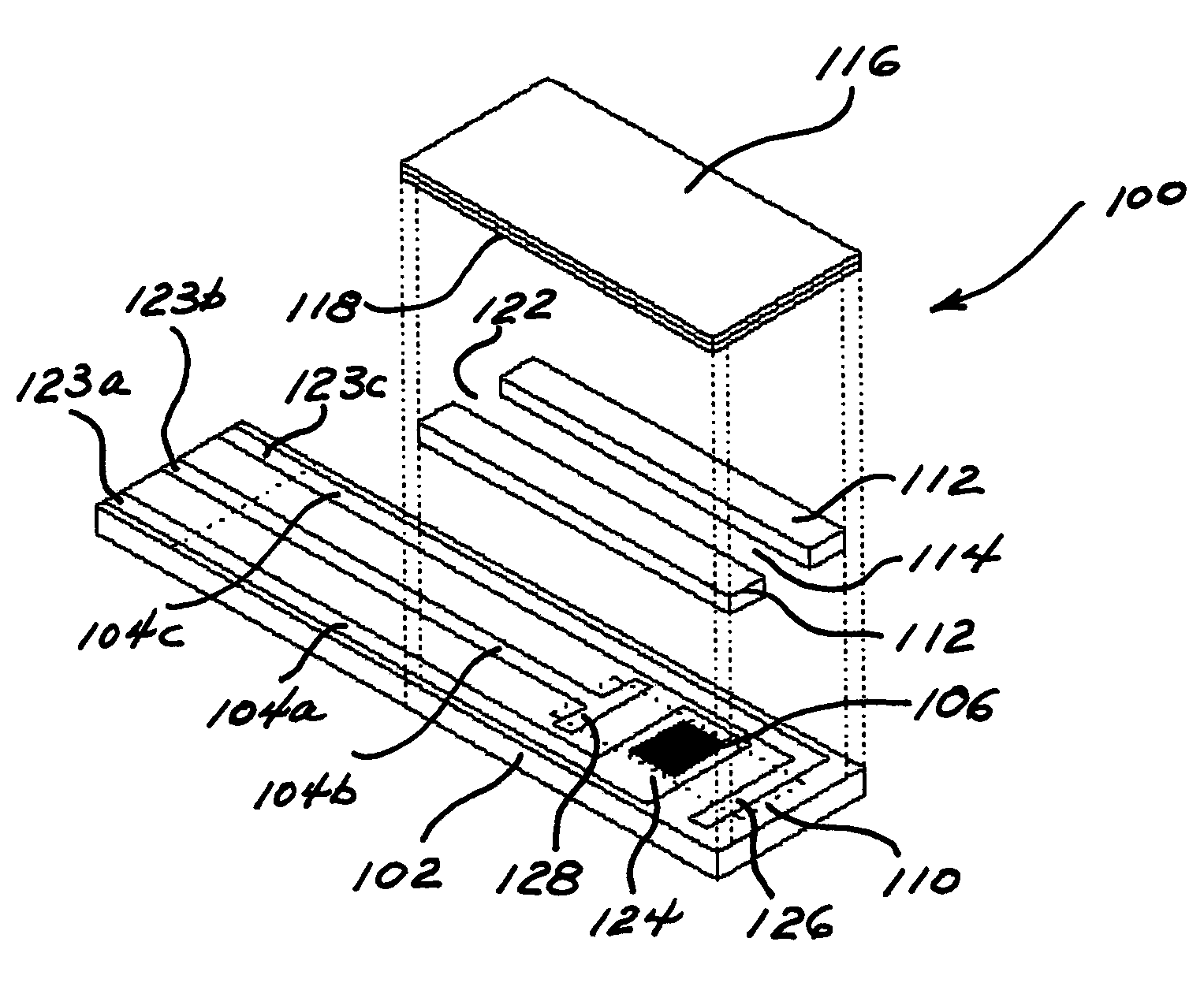
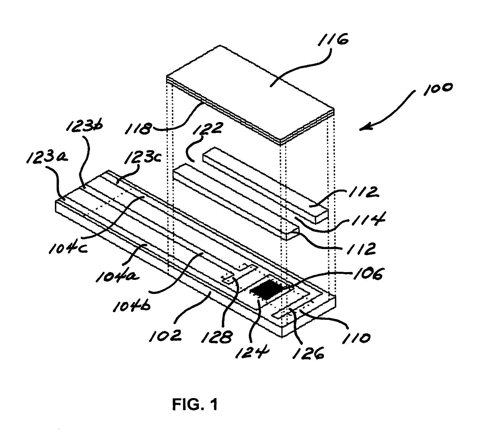
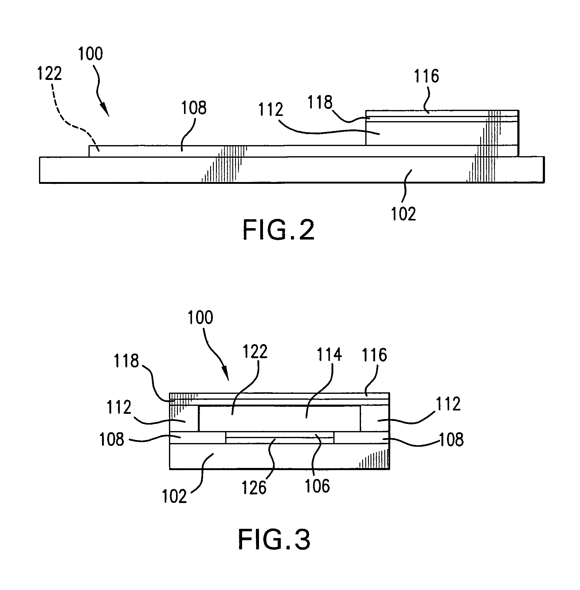
[0076]This example illustrates the preparation of a sensor in the form of a strip according to this invention. The sensor strip of this example is shown in FIGS. 1, 2, and 3.

[0077]Carbon tracks are applied to a base layer made of poly(vinyl chloride) (PVC) by means of a screen-printing technique. The carbon tracks define the position of the electrodes within the reaction site, which includes the reference electrode, a dual-purpose counter / trigger electrode, and working electrode. The counter electrode also functions as a trigger electrode. The assay begins when the sample contacts the dual-purpose counter / trigger electrode. The carbon tracks also define the position of the contacts. A layer of electrically insulating material can be printed over carbon tracks, leaving the defined reaction site exposed. The layer of electrically insulating material is characterized by having a portion cut therefrom to create electrical contacts that can be inserted into a meter for measuring the reac...

example 2

[0080]In this example, the sensor of Example 1 is prepared, with the exception that a mixture of silver and silver chloride is printed on the track leading from the working electrode to reduce the resistance along that portion of the track.

example 3

[0081]In this example, the sensor of Example 2 is prepared, with the exception that a reagent layer is printed on the working electrode. This optional reagent layer comprises an enzyme, a mediator, an optional binder, and an optional filler.


PUM

PropertyMeasurementUnit
thicknessaaaaaaaaaa
thicknessaaaaaaaaaa
widthaaaaaaaaaa

Abstract

A device having a flow channel, wherein a layer of mesh is adhered to a surface forming a wall of a flow channel, but the layer of mesh is of such dimensions that the layer of mesh does not contact those portions of the device where electrochemical reactions occur and electrons flow. In one aspect, the invention provides a sensor, such as, for example, a biosensor, in the form of a strip, the sensor being suitable for electrochemical or optical measurement. The sensor comprises a base layer and a cover layer having a layer of mesh adhered thereto, and the base layer is separated from the cover layer by a spacer layer. The base layer, the cover layer having a layer of mesh adhered thereto, and the spacer layer define a flow channel into which a liquid sample is drawn therein and flows therethrough by means of wicking.

Description

FIELD OF THE INVENTION[0001]This invention relates to a device for improving the flow of a fluid in a channel where the flow results from wicking. More particularly, the invention relates to a sensor for determining the concentration of an analyte in a liquid sample where the liquid sample is transported to a reaction site of the sensor by a layer of mesh.DISCUSSION OF THE ART[0002]Controlling the flow of fluid in a channel where the flow results from wicking is important in microfluidic and microanalytical systems. The volume of fluid in an area where a chemical reaction is to be carried out often is required to be controlled to ensure precise control of the reaction or precise quantification of the analyte of interest or both. When the dimensions of the channel are so small as to reduce the volume of fluid that can be transported in a given period of time, the rapid uptake of viscous fluids, e.g., whole blood, becomes a problem.[0003]The prior art discloses numerous electrochemica...

Claims


Application Information

Patent Timeline
Patent Type & Authority Patents(United States)
IPC IPC(8): G01N11/00G01N27/00C12Q1/00
CPCC12Q1/004
Inventor TESS, MARK E.BAILEY, SCOTT L.KARINKA, SHRIDHARA ALVA
Owner ABBOTT DIABETES CARE INC
Why Eureka
Try Eureka