Resonant converter and control method thereof
a resonant converter and control method technology, applied in the direction of electric variable regulation, process and machine control, instruments, etc., can solve the problems of troublesome circuit design, difficult design and computation of above resonant converter operating frequency, etc., to achieve reliable soft switching operation, continuous soft switching operation, and easy design
- Summary
- Abstract
- Description
- Claims
- Application Information
AI Technical Summary
Benefits of technology
Problems solved by technology
Method used
Image
Examples
first embodiment
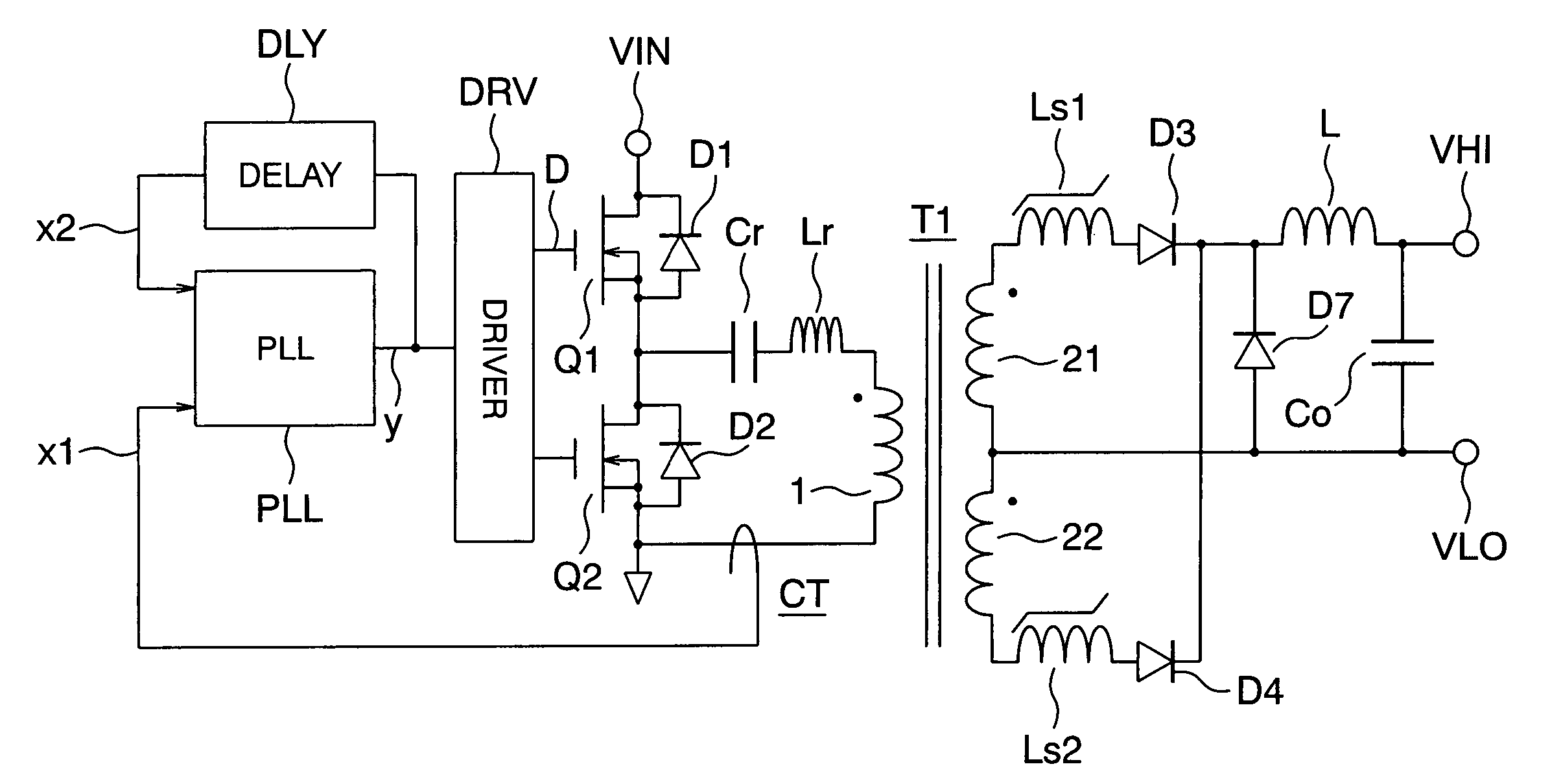
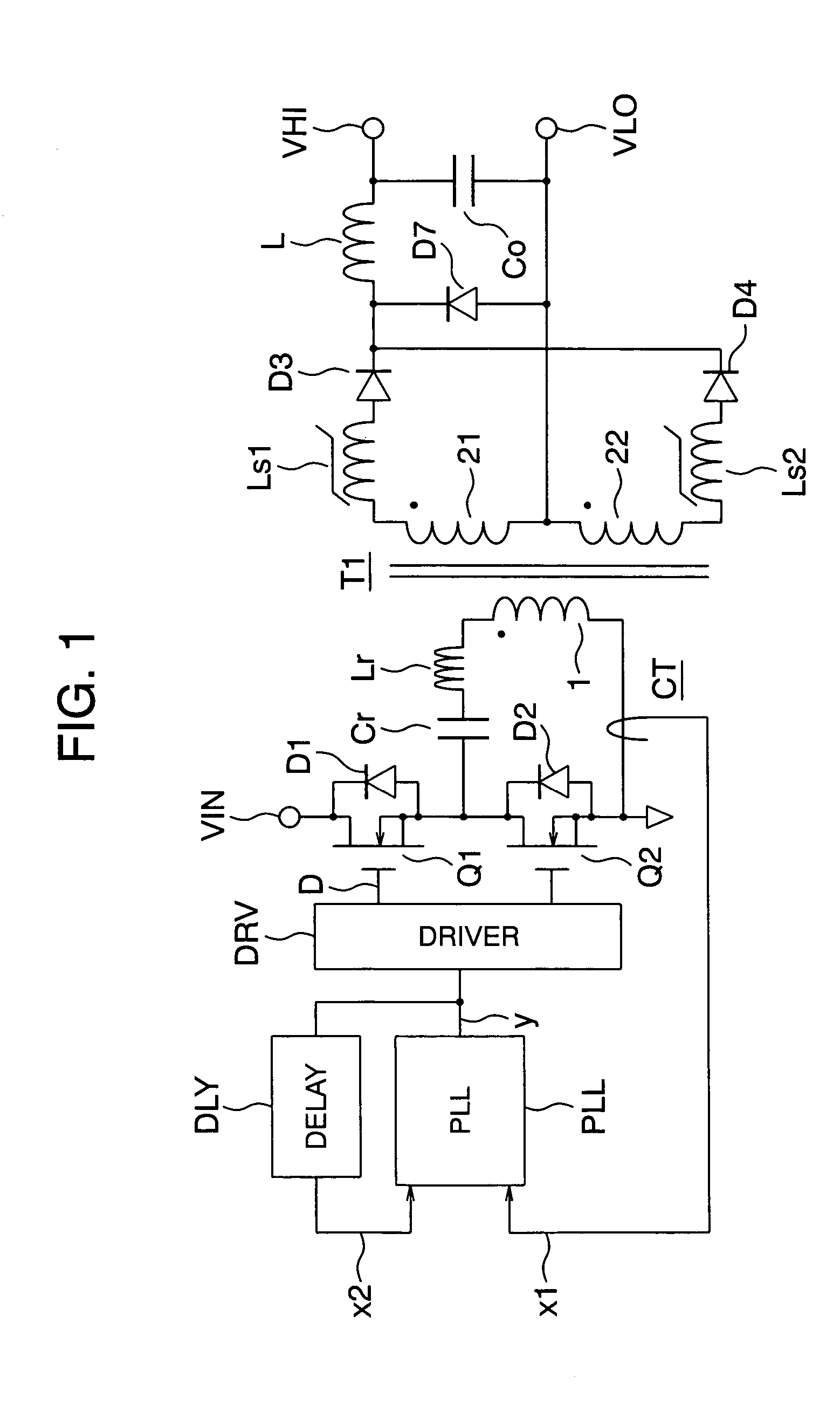
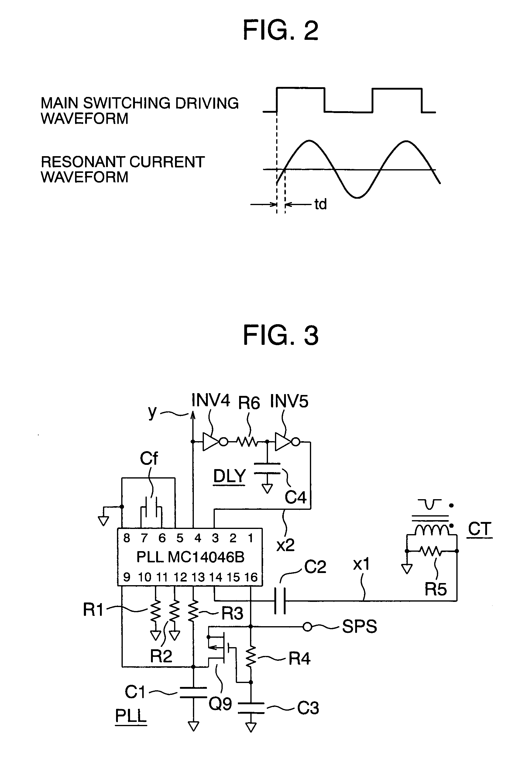
[0029]FIG. 1 is a circuit arrangement of a resonant converter in accordance with the present invention. In FIG. 1, reference symbol VIN denotes an input voltage supply terminal, symbol VHI denotes a high voltage output terminal, and VLO denotes a low voltage output terminal. A high side power MOS FET Q1 is connected to the input voltage supply terminal VIN, and a low side power MOS FET Q2 is grounded. Connected between a midpoint of the power MOS FETs Q1, Q2 and the ground voltage are an LC resonance circuit of a capacitor Cr and an inductor Lr, a primary winding 1 of a transformer T1, and the primary winding 1 of a current transformer CT, which are connected in series. An output of the current transformer CT is connected to an input line x1 as one input of a PLL (Phase Locked Loop) circuit PLL. An output line y of the PLL circuit is connected via a driver DRV to gates of the power MOS FETs Q1 and Q2, and also connected via a delay element DLY to an input line x2 of the PLL circuit ...
second embodiment
[0039]FIG. 4 is a circuit arrangement of a resonant converter in accordance with the present invention, wherein a magamp control circuit is added to the resonant converter of FIG. 1. FIG. 4 is different from FIG. 1 in that resetting diodes D5, D6, a magamp control circuit MAG, and a reference voltage Vref are added for control of the saturable reactors Ls1 and Ls2. The added circuit acts to compare the output voltage and the reference voltage Vref, and perform negative feedback control over the magamp control circuit MAG in such a manner that the output voltage is equal to the reference voltage Vref. When the output voltage is higher (lower) than the reference voltage Vref, the output voltage is fed back to the magamp control circuit MAG to decrease (increase) the output, whereby a desired output voltage can be obtained.
[0040]FIG. 5 is a specific circuit diagram of the magamp control circuit used in the embodiment of FIG. 4. The magamp control circuit MAG is composed of an error amp...
third embodiment
[0041]FIG. 6 is a circuit arrangement of a resonant converter in accordance with the present invention. The embodiment of FIG. 6 is different from that of FIG. 4 in that the diodes D3 and D4 are replaced by power MOS FETs Q3 and Q4. Since the above replacement enables the power MOS FET to have a low on-resistance, the loss can be reduced and the efficiency can be increased when compared with the use of the diodes. Diodes D31 and D41 in FIG. 6 are body diodes for the power MOS FETs Q3 and Q4. The power MOS FETs Q3 and Q4 are driven by gate driving circuit GD1 and GD2 respectively.
[0042]FIG. 7 is a specific example of a circuit arrangement of the gate driving apparatus of a power MOS FET used in the embodiment of FIG. 6. In FIG. 7, a signal extracted from a connection between the saturable reactor Ls1 or Ls2 and the transformer is used as an input to drive a transformer T2 via a level shift circuit of a capacitor C5 and two resistors R9 and R10 and via a buffer circuit BU1. And a volt...
PUM
 Abstract
Description
Claims
Application Information
 - R&D
- Intellectual Property
- Life Sciences
- Materials
- Tech Scout
- Unparalleled Data Quality
- Higher Quality Content
- 60% Fewer Hallucinations
Browse by: Latest US Patents, China's latest patents, Technical Efficacy Thesaurus, Application Domain, Technology Topic, Popular Technical Reports.
© 2025 PatSnap. All rights reserved.Legal|Privacy policy|Modern Slavery Act Transparency Statement|Sitemap|About US| Contact US: help@patsnap.com


